Jennifer Wrigley, Olympus America, Inc.
Custom integration projects have specific
performance requirements that a commercially available microscope alone cannot provide.
Although microscope components are key to the product’s design and performance,
selecting these parts can be confusing. Understanding the key building blocks of
integrated systems and the common nomenclature used by optics manufacturers will
save product developers both time and money during the component selection process.
The best way to start is to review the proposed system and its
intended output. Any or all of three main types of components – optics, illumination
sources and imaging detectors – may be required. Often, standard components
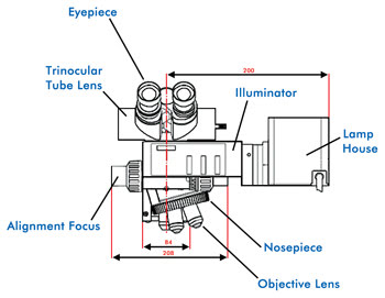
are assembled and custom-mounted together (Figure 1).

Figure 1. A reflected-light illuminator, objective lens, nosepiece
and trinocular viewing tube lens comprise a standard microscope configuration often
used with custom mounting. Images courtesy of Olympus America Inc.
Optics
Not only are performance specifications such as resolution and
transmission important, but also mechanical and space considerations are crucial.
Whether the system must deliver a specified spatial resolution for measurement or
achieve optimal visual contrast for imaging or spectral data, manufacturers use
consistent terminologies when describing optics. These include:
Infinite vs. finite optical systems
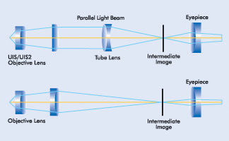
Most optical systems use an infinity-corrected optical design
to make it easier to add intermediate components. In these systems, the intermediate
image plane is formed by the tube lens, so there are parallel light rays between
the objective lens and tube lens. In finite systems, the intermediate image planeis
formed by the objective (Figure 2). Infinite systems allow prisms, sliders and other
components to be introduced without affecting magnification. There is, however,
a fixed range for the distance between the objective lens and tube lens, so it is
wise to ask the supplier for the parfocal length of the objective lens and the focal
length of the tube lens. In addition, knowing the recommended maximum separation
between the tube lens and the objective lens allows the system designer to achieve
maximum performance without affecting illumination uniformity.

Figure 2. Comparison between infinity-corrected (above) and finite-corrected
(below) optical systems.
Numerical aperture
Numerical aperture (NA) describes the inherent ability of an objective
lens to gather light and resolve fine detail. The higher the NA, the better the
resolving power of the lens.1 Objectives with higher NAs tend to be more expensive.
Lateral resolution
Resolution of a microscope is defined as the smallest distance
between two points on a specimen that can still be distinguished as two separate
entities.2 Resolution also depends on the system’s wavelength as defined by
the Rayleigh equation where R is the distance between two adjacent particles, λ is
the wavelength of light and NA is the numerical aperture of the objective.
Working distance
Working distance is the distance between the glass element of
an objective’s mounting structure and a focused specimen. It is an important
consideration when working with topographical samples that have changes in height,
to help avoid any possibility of the objective contacting the sample.
Focal length
Focal length is important for understanding the total magnification
of the system, which is the ratio of the focal length of the tube lens to the focal
length of the objective lens.
To change magnification, the tube or the objective lens can be
changed. In most cases, it is easier to change the objective lens because there
typically is more selection from manufacturers, enabling designers to avoid custom
design costs; in cases where there is a specific objective lens performance characteristic
that must be preserved, the tube lens can be changed.

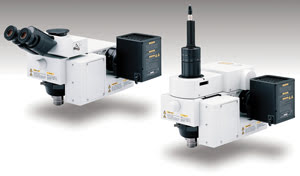
Figure 3. Example systems
based on standard optical components for integration into larger pieces of equipment.
The system on the left shows a tube lens with eyepieces for operator viewing, and
the system on the right includes an autofocus unit and a tube lens with a direct
camera mount.
Transmission
Most objective lenses are designed for peak transmission at a
specific wavelength. Outside of this range, performance can drop off significantly,
so matching the system wavelength to the appropriate objective is critical to system
performance. Many objective lenses are corrected for the visible light spectrum
(400 to 700 nm). Other specialized objectives peak in the ultraviolet (<400 nm)
or infrared (>700 nm) ranges.
Illumination sources
Depending upon the system, illumination may come from a laser,
fiber optic lightguide, or standard halogen or mercury bulb. There are three key
factors in selecting the appropriate light source for a system.
First is the wavelength and size of the light source. The wavelength
must be complementary to the output. Additionally, the light source must provide
sufficient energy to transfer through the system and be returned to the sensor.
Second are the optical characteristics of the system, including
projection lens magnification and the exit pupil diameter of the objective lens.
Each projection lens assembly has a magnification that optimally projects the light
to the back focal plane of the objective lens. Current practice for spatial measuring
and imaging systems is to use Köhler criteria, to provide even distribution
of light from the source across the back focal plane of the lens, but some systems
use critical illumination – which relays the illumination source directly
to the back focal plane – for optimum efficiency when gathering spectral data.
The exit pupil should be entirely filled by the illumination, and pupil diameters
vary from objective to objective. Many manufacturers may provide projection lens
magnification and exit pupil – back focal plane location – diameters
so that the illuminator/projection lens can be matched to the objective lens.

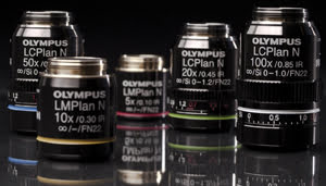
Figure 4. Both the optical performance and the mechanical dimensions of objective lenses must be considered in the overall design. The differences in mechanical dimensions of an objective lens series can
be seen.
Third is the type of illumination. For metrology, fiber optics
and standard halogen lamphouses are commonly used. For applications requiring high-intensity
light, a metal-halide power supply can be more effective than traditional mercury
bulbs. High-intensity light sources, with their longer bulb life and better illumination
stability, use coherent fiber guides. Collimating adapter lenses are used to optimize
the light path from the fiber guides through the optics of the microscope by focusing
the light into parallel rays.
Another illumination source gaining in popularity is the LED,
which can be automated for simple intensity control and fast on/off switching. LEDs
offer high reliability, long lifetimes and low energy usage, making them both practical
and better for the environment. An additional advantage of LED illumination is that
there is no change in color temperature when adjusting the voltage, so the system
maintains continuous color fidelity, unlike traditional halogen sources that appear
yellow at low-voltage power levels.
From an integrator’s standpoint, there are other factors
to consider. Each optical component or detector is rated to withstand a certain
amount of energy or heat. When working with high-power illumination sources such
as lasers, it is important to identify any limitations of the optical coatings or
other structural elements. For temperature-sensitive samples, it is desirable to
remove as much heat as possible. Using an external light source such as a fiber
guide and a cooled power supply or LED illuminator removes heat from the system,
helping to preserve the sample’s integrity.
Imaging detectors
Not all systems require imaging components, but for many applications,
it is standard to view, capture and create an imaging database. If imaging is the
primary means for data collection, having the right detector is vital. The following
are some parameters to consider when selecting a suitable digital imaging device:
Digital resolution
Many people are misled into thinking that, when it comes to megapixels,
bigger is better; i.e., that having more megapixels means gaining better resolution.
Ultimately, designers must match the optical resolution of the microscope system
or spot size projected on the CCD with the digital resolution of the camera to avoid
over- or under-sampling. The spot size of the projected image is dependent upon
the objective lens magnification, numerical aperture, relay lens design and tube
lens. The resolution of the CCD depends on both the size and number of pixels. The
desired optical resolution should be considered first, and then digital spatial
resolution should be determined, as it is the limiting factor in achieving the system’s
overall resolution. This phenomenon is explained by Nyquist’s criterion, which
says that two to three pixels on a CCD chip are required to resolve the smallest
feature that the optical system can reproduce. Using a smaller number of pixels
results in image degradation. A larger number of pixels does not assist in resolution
and may be more costly.
Dynamic range
Dynamic range relates to the ability of the sensor to collect
data at very low and very bright levels simultaneously.
Spectral response
Just as it is important to match the wavelength of the emitting
light source with the peak performance range of the objective lens, it also is important
to match the light source to the detector. An imaging device’s spectral sensitivity
is measured by its quantum efficiency, which is the probability that the detector
will detect a photon of a given wavelength, expressed graphically.
Cooled vs. uncooled
Depending upon the application, cameras may require cooling. Options
include liquid nitrogen, water, air and Peltier thermoelectric cooling. Some of
the choices require additional space and/or external equipment. Cooled cameras are
more sensitive at low light levels and usually are more expensive.
Integration considerations
A digital camera requires software to operate. Computer and interface
options include such standards as PCI, USB, FireWire and Ethernet, all of which
have advantages and disadvantages. Data collection from the digital camera also
may have to be synchronized with external hardware devices such as a mechanical
shutter or laser pulse.
Understanding the basic building blocks of optical and digital
microscopy, the application’s design parameters and how they are interrelated
can help developers ensure that integrated systems meet the needs of their users
in the most efficient and effective way. Besides technical specifications, it is
vital to work with manufacturers with OEM integration experience, as careful dedication
and planning are necessary to provide controlled pricing and to meet demanding delivery
logistics throughout the product life cycle.
Meet the author
Jennifer Wrigley is associate product manager at Olympus America
Inc. in Center Valley, Pa.; e-mail: [email protected].
References
1. www.olympusamerica.com/seg_industrial/files/industrial_component_guide.pdf.
2. For more information, consult: www.olympusmicro.com/primer/anatomy/numaperture.html.