Technological advances enable the Michelson interferometer to measure multilayered samples that are tens of millimeters thick, with submicron accuracy.
SAM MARGOLIS AND MICHAEL HOUK, BRISTOL INSTRUMENTS INC.
White light interferometry (WLI) is a common system of measurement with a long history and a variety of applications, which currently include surface profiling1, medical imaging, and — as in the past — thickness measurement. Also known as coherence scanning interferometry (CSI), vertical scanning interferometry (VSI), and optical coherence tomography (OCT), these systems, regardless of their names, are characterized by the same components: a broadband light source, reflection from one or more surfaces being measured, illumination and light collection optics, and an interferometer or spectrum analyzer (Figure 1).
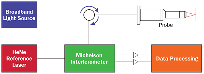
Figure 1. A block diagram of a Michelson-based OCT system. Courtesy of Bristol Instruments.
Industrial application of WLI dates back to before 1966 when P.A. Flournoy was granted a patent for his interferometric optical phase discrimination apparatus2. This system used a tungsten filament lamp, free-space optics, and analog electronics to monitor film thickness during manufacturing.
In the decades since Flournoy’s invention, although the basic science has remained the same, there have been technological advances in light sources, including the helium-neon (HeNe) laser and the superluminescent light-emitting diode (SLED); advances in fiber optics; and advances in digital electronics that have increased the measurement accuracy, precision, and maximum depth of time-delay-based WLI measurements.
The scanning Michelson interferometer, the heart of Flournoy’s system, continues to be an integral part of many state-of-the-art instruments, including optical spectrum analyzers, wavelength meters, and, most recently, gravitational wave detectors. Although limited in speed due to the movement of an optic within the interferometer, the scanning Michelson interferometer continues to be capable of making highly accurate measurements of multilayered materials, and now with submicron accuracy.
The Michelson interferometer
The design of today’s WLI systems are determined by the intended application. For example, systems with 2D sensor arrays are typically utilized for surface profiling because the array of detectors allows rapid collection over a wide area. A scanning Michelson interferometer, with a fiber-coupled confocal objective, is specifically designed for depth measurement applications.
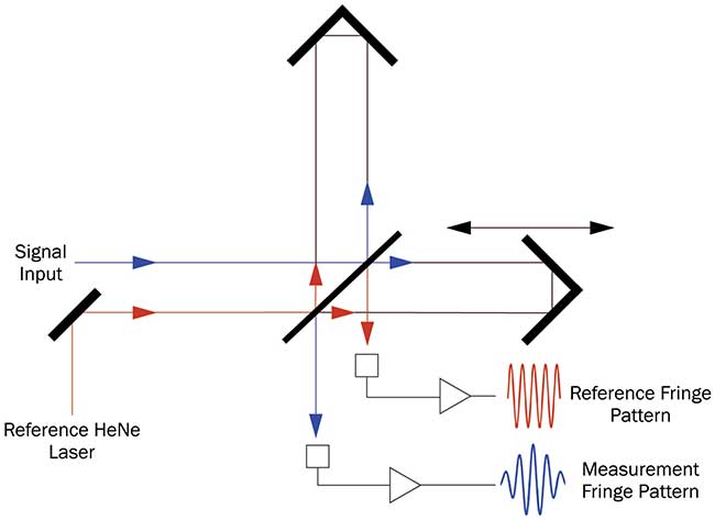
Figure 2. A diagram of a Michelson interferometer with parallel reference and signal detection. Courtesy of Bristol Instruments.
The Michelson interferometer is the key component in the WLI system and is where the measurement data is collected. One arm (path) of the interferometer has a time-varying delay, resulting in a detected signal that is the autocorrelation of light’s complex field (Figure 2). A wide bandwidth light source, which has a narrow coherence function, will only produce interference fringes when the difference in the two paths of interfering light is less than the width of the coherence function. The coherence function can be quite narrow, on the order of microns. This means that as the path length difference, or delay, changes, a “burst” of fringes appears at the interferometer output.
The fringe burst center is a very precise indicator of the moment when the interferometer paths are equal for any given reflection. By relating the position of the fringe burst center with the position of the scanning arm, the separation of the interfering reflection can be determined (Figure 3).
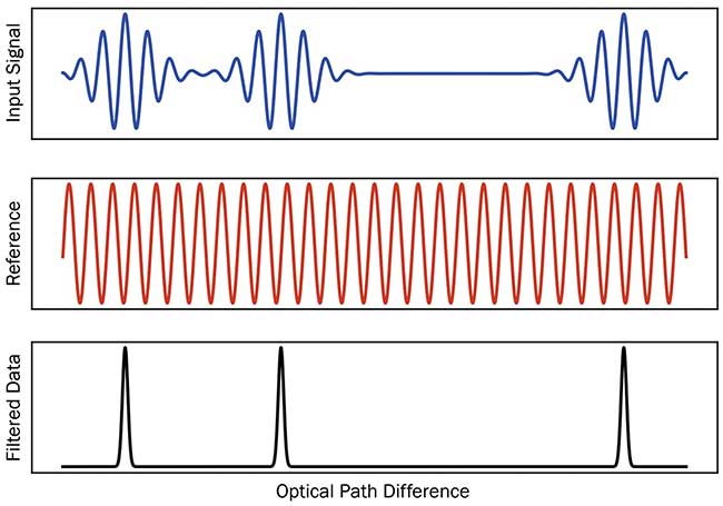
Figure 3. A depiction of signals recorded from a scanning Michelson-based thickness measurement: modulation transfer function (MTF) versus surface irregularity. Courtesy of Bristol Instruments.
When multiple surfaces are reflecting broadband light, multiple fringe bursts appear in the interferometer whenever the delay between any pair of reflections is compensated by the difference in length of the interferometer.
Accuracy and efficiency
The most fundamental improvement in the accuracy of the WLI systems occurred in 1976, with the addition of the HeNe laser. HeNe lasers have been an internationally recognized reference for length for four decades, and, when used in a Michelson interferometer, they are essentially the ruler against which measurements are made. HeNe lasers are, unlike distributed feedback fiber Bragg diode lasers, insensitive to changing environmental conditions and age, and provide the advantage of exceptionally accurate tracking of the changing optical path.
The interferometer can be in air, which has very low dispersion (difference in optical path due to wavelength), so any differences in path length between the reference light source and the measurement light source may be corrected for by monitoring the air temperature and pressure. Residual errors are then at the parts-per-billion level.
Also important to enabling widespread use of OCT instruments has been the development of SLEDs. SLEDs, miniaturized and efficient broadband light sources, are very bright light-emitting diodes optimized to have broad and Gaussian spectral output. SLEDs have nearly ideal Gaussian spectra, and are bright enough to couple into optical fiber, making them ideally suited to OCT. The use of optical fiber itself is both convenient and inexpensive, and enables the instrument to be separated from the measurement location.
Using optical fiber also improves lateral resolution by allowing for diffraction-limited confocal illumination and collection of the reflected light. Furthermore, the fiber end provides an ideal reference reflection, which is well separated from the reflections from the surfaces of the measurement sample3. This allows multilayer materials to be measured unambiguously.
The ongoing development of dedicated digital signal processors enables real-time data processing at even faster speeds to be built into the OCT instrument. Particularly in instances with high sampling rates, where single measurements are made from >100,000 samples, having an internal high-speed processor means that an external computer is not required for complex processing tasks, and is only needed for communicating results from the instrument. With analog-to-digital converters, and digital signal processors operating at MHz data rates, multiple measurements per second can be processed in real time inside the instrument.
Making accurate instruments requires the ability to verify performance. To prove accuracy, the industry uses conventional metal gauge blocks. The modern standard for gauge block height is to measure the height of a block from the surface of an optical flat, onto which the block is wrung. The metal blocks are not transparent, so they cannot be measured directly, but a second optical flat can be wrung onto the top surface, allowing the distance between the two flats to be measured through the hole in the center of the block. A well-built interferometer, using a HeNe laser as a reference, will not need any calibration to achieve <0.10-µm measurement uncertainty.
Taken together, these advancements mean that there are OCT instruments now available that are fast and accurate, that can be remotely located via fiber optic cable from the measurement location, and that integrate well into modern labs and manufacturing environments.
Application
Accurate and nondestructive optical thickness measurements are necessary in a range of applications, including thick optics (tens of millimeters); thin optics, such as contact lenses; composite materials, such as touchscreens and other laminated products with optically clear adhesives; and medical- or precision-grade tubing.
Measurements of center thickness and sag of soft contact lenses, for example, are very challenging. The lenses can easily be deformed and must be measured while immersed in saline solution. The measurement can be performed by placing the lens in a “wet cell.” Because the solution and the lens have indices of refraction that are very close, the lens appears nearly invisible, precluding the use of an optical microscope and traveling stage.
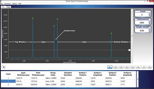
Figure 4. An example of a measurement of a soft contact lens immersed in saline solution. Courtesy of Bristol Instruments.
Interferometric measurements, on the other hand, are highly sensitive because the electric field is detected rather than just intensity, and the depth resolution is a function of source coherence length, rather than depth of focus, as in conventional microscopy. Not only is the WLI measurement accurate, it can be carried out without touching the sensitive lens surface. Although the lens may only be 100 µm thick, the manufacturer can also determine the lens sag by measuring the distance from the lens to the wall of the wet cell, which may be several millimeters away (Figure 4).
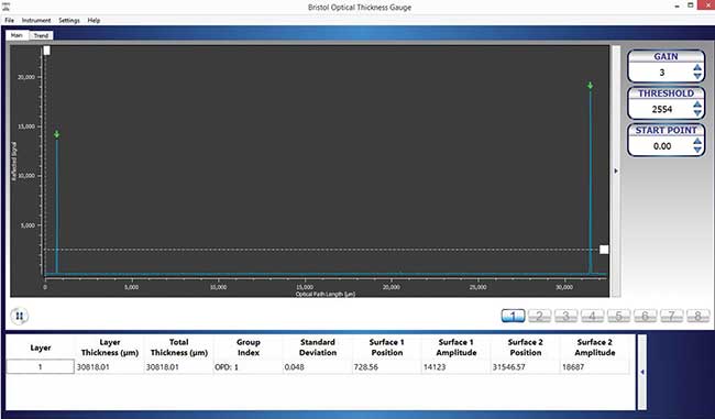
Figure 5. An example of a measurement of a thick optic. Courtesy of Bristol Instruments.
Multilayered materials can also be measured nondestructively, allowing process control for manufactured items, which previously could only be measured destructively. Examples include materials such as laminated composites used for touchscreen displays, compound lenses, and bonded or air-spaced optics. Other optical lenses can also be measured during production, allowing, for example, lenses cut on lathes to be monitored in process. Lenses tens of millimeters thick can be measured as long as the interferometer is designed with enough travel (Figure 5).
Challenges
Despite many unique advantages, there are still challenges to the practical application of this technology, specifically as it relates to materials, such as those that are rough, scattering, or absorbing. The confocal illumination and light collection optics allow excellent lateral resolution and rejection of stray light, but also require that the surfaces be normal to the incident light in order for that light to be coupled back into the instrument. The angular acceptance of the objective is proportional to its numerical aperture (NA), while the maximum thickness is limited by the depth of focus, which is inversely proportional to NA. Therefore, very thick samples will typically require very low NA objectives, and the sample surfaces must then be coplanar and well aligned with the optical probe. Different probes with different NAs are available to optimize light collection for different sample geometries. With a well-chosen objective with proper alignment, there will be adequate signal in the interferometer and no effect on accuracy.
Light collection may also be stymied by absorbing and scattering materials that attenuate the beam as it travels both to and from each surface. In addition, scattering and very rough surfaces can present the interferometer with overlapping coherence functions, which convolute the surface location and make the true locations for the surface somewhat ambiguous. Accurate measurements are typically only possible with transparent materials that have distinct interfaces.
Vibration can also cause measurement errors. While the reference mirror in the interferometer is scanning, the instrument is recording the displacement of that mirror between surfaces. If the part being measured is in motion during the time that each surface is identified by the interferometer, that movement will directly add error to the measured thickness and so must be kept under control.
WLI is uniquely qualified to make accurate measurements of the thickness of a wide range of transparent objects. What is considered state of the art for optical thickness measurement has advanced significantly since WLI’s invention more than 50 years ago. Instruments now are capable of measuring tens of millimeters, multiple layers, and very faint reflections, with absolute accuracies, to less than a tenth of a micron.
Meet the authors
Sam Margolis has an M.S. in optics from the University of Rochester and a B.S. in glass science from Alfred University. His primary role is R&D engineer for Bristol Instruments’ Optical Thickness Gauge product line; email: [email protected].
Michael Houk has a Ph.D. in optical engineering from the Institute of Optics at the University of Rochester. During his career, he has developed a multitude of Michelson interferometer-based precision instruments; email: [email protected].
References
1. P. de Groot and L. Deck (1995). Surface profiling by analysis of white-light interferograms in the spatial frequency domain. J Mod Opt, Vol. 42, pp. 389-401.
2. P.A. Flournoy (May 16, 1967). U.S. Patent Number 3,319,515.
3. M.N. McLandrich, D.J. Albares, and S.A. Papper (Aug. 23, 1994). U.S. Patent Number 5,341,205.