A novel optical device offers multiple detection benefits for light source and luminaire characterization as well as for surface scatter measurements.
Ron Rykowski and Kevin Chittim, Radiant Imaging Inc., and
Sipke Wadman, Royal Philips Electronics Nederland BV
Many photonic applications require the ability to calculate luminous intensity; that is, light intensity as a function of angle. For example, measuring output as a function of angle helps characterize light sources, luminaires and displays, and the angular distribution of scattered light from a surface is used to assess surface roughness for products as diverse as paper, painted metal, protective films and high-performance optics.
Performing these measurements traditionally has meant slowly sweeping a single detector through every angle of interest, or scanning only at a finite number of the most important angles. Now a new type of optical device, called the imaging sphere, enables the acquisition of an entire hemisphere (2π steradians) of angular intensity information in a single scan.
The imaging sphere
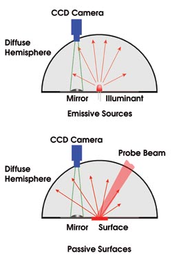
The main optical elements of the imaging sphere are a coated, diffuse, low-reflective hemisphere, a curved secondary mirror and a CCD camera (Figure 1).

Figure 1. Light from an emissive element placed at the aperture of the “imaging sphere” strikes the device’s inner surface and is reflected by a convex mirror into the lens of a CCD camera (top). The resulting image is of the entire inner surface and contains the data necessary to create a profile of the angular intensity of the illuminant. To test a passive material, a probe beam is reflected off its surface (bottom) or, if it is translucent, shone through from behind (not shown).
The hemisphere is attached to a flat, nonreflecting baseplate that has a small aperture at its center. Light enters the device through this aperture, strikes the coated inner surface of the hemisphere and is reflected by a convex mirror into the lens of a CCD camera. The mirror permits the camera to image the entire inner surface of the hemisphere — seen as an illumination pattern — at once. The image thus contains all the information necessary to reconstruct the entire angular intensity profile of the illumination at a resolution determined by the camera’s sensor.
A key element to successful operation of the imaging sphere is the inner coating of the hemisphere. Conventional integrating spheres use a highly reflective "white" coating that causes strong diffuse reflections and weak specular ones. The effect is that multiple reflections cause the spatial and angular structure of the light to be efficiently scrambled. The intensity is deliberately integrated and averaged, resulting in an even light distribution that can be used as a Lambertian source or for the measurement of integrated light flux.
On the other hand, if the inner coating were mirrorlike, specular reflections would dominate. The collected light would be directed to a spot focus and not be collected by the camera.
Instead, the imaging sphere uses a gray (reflectivity of 18 to 20 percent) coating designed to deliver only diffuse (scattered) reflections. The baseplate is coated black to approach zero reflectivity. As a result, the CCD camera sees an intense image of the first-order illumination pattern with a very weak, uniform background created by second and beyond strikes. This background level depends on the total light flux. Typically below 1 percent of peak image intensity, it can easily be subtracted out by the device’s software.
Because the secondary mirror is a spherical convex type located away from the center of the hemisphere, the image acquired is actually a distorted, off-axis view of the inside of the dome. Nonetheless, it is a complete view of the hemisphere’s inner surface. For angle-calibrated imagery, it is necessary to convert this image into an undistorted view and to provide the data in a useful format, depending on the application. System software developed by Radiant Imaging Inc. performs these transformations, which are somewhat equivalent to a look-up table, converting the spatial intensity information in the image into angular intensity information in the hemisphere.
Image Processing
The software takes the raw intensity/angular information and computes functions useful for a variety of applications. In scatterometry, for example, the software can deliver detailed calculations of total integrated scatter and bidirectional reflective distribution function or bidirectional transmissive distribution function, which describe reflected light intensities in elevation and direction angles (φ and ϑout ) for a given set of illumination angles (ϑ and ϑin ).
Although the details of these software transformations are beyond the scope of this article, several aspects merit brief mention. Most importantly, the software offers several dimensions of calibration that can be optimized at the factory or by the user: It enables data to be calibrated for dome or camera size and for mirror location, i.e., to correct image distortion. And it provides flat- or cosine-field and offset calibrations to match the application’s brightness and background conditions. Importantly for source/luminaire metrology, the software also permits quantitative calibration of the system response for color in commonly used color coordinates such as CIE.
Sources and luminaires
Applications for the imaging sphere include characterization of emissive sources and illuminated surfaces and materials. Many sources require measurement of both the luminosity and chromaticity of their output as a function of angle. Examples include liquid crystal displays, plasma display panels, LED and organic LED displays, and backlights based on LEDs, lamps and cold cathode fluorescent lights.
CCD cameras have already affected luminosity and chromaticity measurements, bringing imaging capabilities to a field that formerly relied on spot photometers and colorimeters. For instance, a number of application-specific turnkey solutions can provide uniformity data over extended sources such as flat panel displays, simultaneously measuring the effective performance of every pixel in the display.
Until now, performing chromaticity and luminosity measurements as a function of viewing angle required mounting a detector or instrument on orthogonal goniometers to sequentially sweep through all the angles of interest. When used with a CCD camera, this technique has the advantage of delivering both spatial and angular source information; however, it is time-consuming, expensive and not well-suited to high-volume quality control and assurance or production measurements, where a significant amount of product must be sampled in real time.
Typical applications that benefit are production sampling and quality control and assurance of LEDs. These are small, inexpensive components, but even the highest-performance varieties do not justify the time and expense of goniometric characterization. However, they do require production-level quality control because they tend to exhibit significant variation in performance.
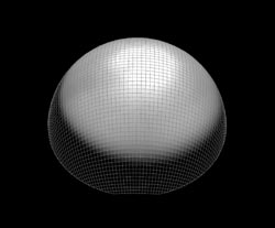
In LED production, a small die is machine-encapsulated in a tiny package together with a lens. Slight changes in the way the product is assembled can produce very different irradiance profiles. The imaging sphere is suitable for performing quality control measurements because it provides complete characterization of the irradiance profile in a few seconds (Figure 2).

Figure 2. The imaging sphere is suitable for LED quality control metrology, as it provides complete characterization of the irradiance profile within 15 seconds. An actual measurement of an LED light distribution projected in a hemisphere shows a bright center and a bond wire shadow.
In the case of such extended sources as flat panel displays, angular information from the entire panel can be rapidly accumulated by scanning the subject under the sphere’s aperture.
It also is important to note that the sphere provides complementary data and is much faster when compared with goniometric methods. Specifically, goniometric tools tend to have a large working distance and provide mostly far-field information. In contrast, the imaging sphere involves a smaller sampling radius to extract mainly far-field data. Using an additional imaging mode, it also can provide near-field data.
Surface scatter applications
The imaging sphere is expected to have an even bigger impact in scatterometry, an area that traditionally has been limited by available technology and that has delivered more promise than it has practical, widespread benefits, with the exception of a few niche applications.
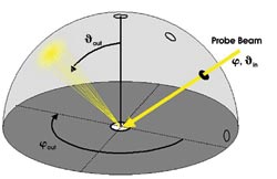
The basic idea behind scatterometry is straightforward: A collimated light source, such as a white-light beam or a low-power laser, illuminates a small spot on a surface. If the surface is nontransmissive, the reflected light will be a combination of both the specular and diffuse components (Figure 3).

Figure 3. If a passive surface is nontransmissive, the reflected light is a combination of the specular and diffuse components. A bidirectional reflective distribution function computes the intensities reflected toward outgoing azimuth (φ) and elevation (ϑ) in the hemisphere.
The intensity and angular distribution of the diffuse scatter are determined by the surface roughness — both the period and the amplitude of surface imperfections — just as with a diffraction grating. The scattered light intensity can provide key data about the surface profile.
Important parameters are the total integrated scatter and the bidirectional reflective distribution function, which is a normalized, two-dimensional description of the scatter profile. These data help with the derivation of such physical parameters of interest as the arithmetic mean surface roughness.
In the case of transmissive materials, the light scatters forward and backward. Forward scattering can be measured by illuminating the sample from behind. In this case, the important parameters are the bidirectional transmissive distribution function and the total integrated scatter. These provide information about surface roughness and the density, size and distribution of particles, cracks and other inclusions within the target material.
Surface roughness and material scattering are of interest to many industries and technologies for both cosmetic and functional reasons. For example, in the automotive industry, variations in metallic paints or interference-effect lacquers affect the perceived visual quality of vehicles. In terms of impaired functionality, examples include products as diverse as coated paper and plastic injection molds. Paper that does not meet a certain surface standard may not yield a high-quality printed image. Injection molds with worn decorative textures can produce products with a bad appearance.
Moreover, scatter is not just about physical products. Scatter also helps to evaluate processes, such as how effectively a new window cleaning fluid eliminates visual streaks on test samples.
These products and processes can be monitored, verified, specified or optimized only with a measurement tool. Traditional scatterometry instrumentation consists of high-performance laboratory equipment that relies on a spot detector mounted on a goniometer, or a handheld device with one or two detectors at key fixed angles. The goniometric method is too slow and expensive for production use and quality control, and the latter yields reliable data only within certain constraints, resulting from a very limited data set. The imaging sphere completely changes this situation by economically combining a comprehensive data set and high speed.
The sphere provides a compact and reliable solution to many problems that require measurement of light intensity as a function of angle. The rapidness of this technique, combined with its ability to work in normal ambient lighting conditions, makes it particularly suited for production environments. And while applications exist for 300-mm-diameter or larger spheres used with cooled, low-noise CCD cameras, there is potential for many small, perhaps even handheld, instruments based on this technology.
Radiant Imaging and Royal Philips Electronics Nederland will support these applications by licensing the technology to instrument, system and tool builders who have an established presence in key markets and who provide complementary measurement capabilities.
Meet the authors
Ron Rykowski is president and Kevin Chittim is vice president of Radiant Imaging Inc. in Duvall, Wash.; e-mail: [email protected].
Sipke Wadman is senior scientist at Royal Philips Electronics Nederland BV, Philips Applied Technologies, in Eindhoven, the Netherlands.