Fluorescence lifetime imaging microscopy (FLIM), which measures the spatial distribution of the fluorescence decay, can be achieved either in the time or in the frequency domain. Each approach exhibits advantages and disadvantages, depending on the type of light detector and acquisition method employed.
GERHARD HOLST, Excelitas PCO GmbH
The term fluorescence is often applied as a synonym for photoluminescence, although luminescence actually covers fluorescence and phosphorescence. Both of these terms describe the process of absorption of light at a higher energy and subsequent re-emission at a lower energy. In this article, the terms fluorescence and photoluminescence will be considered interchangeable. Depending on the dye, the absorption of photon energy is not instantaneous. The absorption instead requires a finite amount of time, and the same also applies to the emission process, in that the dye continues to emit light for a short period of time after cessation of the excitation. Termed decay rate or lifetime, this emission decay process is a fundamental property that characterizes the dye, along with its specific spectral behavior.
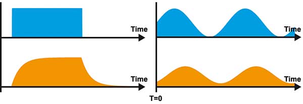
Figure 1. The time responses of light signals for excitation light (blue) and luminescence emission (orange).
The left signals show the time response in the time domain. If the
luminophore is excited with a light pulse of rectangular shape, the
emission shows a characteristic rise and decay shape. The right signals
show the time response in the frequency domain. If the luminophore is
excited with a continuous sinusoidal light signal, the emission shows a
change in amplitude and constant part plus a delay compared to the
excitation. Courtesy of PCO AG.
The emission process can always be described by an exponential decay over time, although, as often as not, several exponential factors may be required to properly describe the observed behavior. The fluorescence lifetime can provide additional information about the dye or about its immediate environment, and the predictability of this behavior is often used as the basis for sensing applications.
There are, for example, fluorescence dyes that, following excitation, nonoptically transfer their excess energy to another dye molecule if it is nearby, resulting in a so-called Förster resonance energy transfer (FRET). FRET shortens the decay rate and is used to measure interactions between the molecules, indicating, for example, processes like dimerization of proteins as intracellular behavior. FRET, as a measuring method, is well-established to investigate intracellular processes. Unfortunately, the two dyes — a donor and an acceptor of the energy — used for FRET must have overlapping spectral properties to act as a FRET pair. The standard measuring process is consequently more time-consuming because the donor fluorescence has to be measured before and after the acceptor has been bleached to determine the required measurement of the FRET efficiency. This efficiency is a measure of how near the two molecules have been. An alternative method would be the measurement of the donor fluorescence lifetime, because the comparison of these results to the lifetimes of control experiments delivers the same information.
Camera-based systems that are capable of measuring the spatial distribution of fluorescence decay have been described in the literature since the start of the 1990s. In the meantime, the acronym FLIM has become the established term for fluorescence lifetime imaging or fluorescence lifetime imaging microscopy.
How is a fluorescence lifetime image acquired? From a technical standpoint this can be achieved either in the time or in the frequency domain, with each approach exhibiting both advantages and disadvantages, depending on the type of light detector and acquisition method employed.
FLIM in the time domain
Figure 1 illustrates an ideal response of the fluorescence over time following cessation of the excitation. The fluorescence decay can be acquired via a variety of methods, and it is then modeled with appropriate decay times. In general, one either already knows how many lifetimes are to be expected, or the model is reiterated until the best fit is obtained.
For imaging applications, which measure the spatial distribution of the lifetime, scanning methods are employed. Time-correlated single photon counting systems, as seen on the market today, is the established approach for weakly emitting dyes. Alternatively, a camera can be used to integrate the fluorescence emission over a short portion of the decay curve, where the spatial distribution of the lifetime is then calculated in combination with one or more such acquisitions over further portions of the decay curve. Photon counting is a highly sensitive method and is best-suited to weakly emitting dyes. Appropriate systems must exhibit adequate bandwidth so that the oftentimes very rapid light emission and correspondingly short lifetimes are measured accurately and are not distorted. Such measurement systems are available, for example, from Photonic Research Systems.
One application is the measurement of the distribution of the oxygen partial pressure across a planar sensing foil, which is positioned in contact with the sample that should be investigated, for a piece of coral or a marine sediment. In the example in Figure 2, a piece of coral was placed on top of an oxygen sensing optode (optical chemical sensor) and the oxygen distribution below the coral skeleton was measured after the coral had been exposed to light2. The activity of the bacteria living in the coral skeleton can be seen by their light-induced generation of oxygen. Figure 2 shows the oxygen distribution in the water below the coral after an exposure to light in percent air saturation (false color coded).
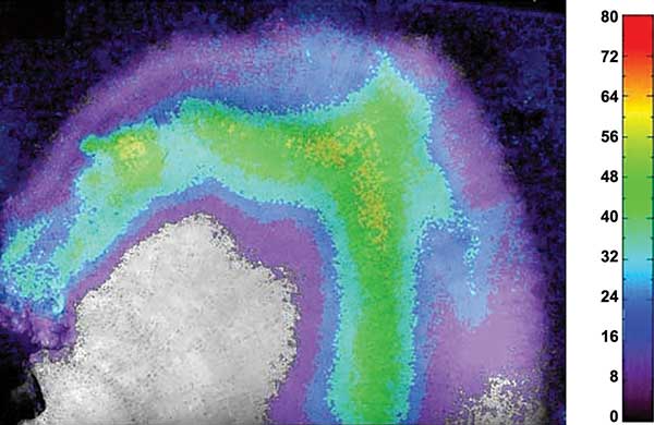
Figure 2. Black-and-white image of a piece of a Porites coral with the false color coded distribution of oxygen across the coral skeleton caused by the oxygen production due to photosynthesis of the algae living in the coral skeleton. The sample had been illuminated before. The oxygen scale is given in percent air saturation of the water. Courtesy of PCO AG.
FLIM in the frequency domain
In the measurement of FLIM in the frequency domain approach, dye fluorescence is excited with continuously modulated light. Taking, for simplicity’s sake, a sine wave modulation of the excitation, the fluorescence from the dye follows this modulation, although it is delayed because of the dye’s excited state lifetime. Figure 3 depicts both the excitation (blue) and the fluorescence light (orange). The fluorescence also exhibits a different ratio of the modulated component to the (constant) background intensity, compared to that of the excitation light. The delay is technically termed the phase angle or phase angle delay (Φ), while the aforementioned ratio is termed the modulation index (m). Both of these parameters can be determined by appropriate sampling of the signal.
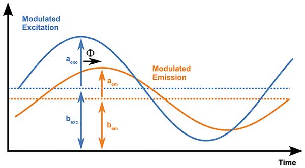
Figure 3. Characteristic parameters describing the involved sinusoidal light signals: excitation amplitude (aexc) and constant part (bexc), emission amplitude (aem) and constant part (bem), and the time delay or phase angle (Φ). Courtesy of PCO AG.
By acquiring an image at each of four different sampling points, then spatial distributions for the fluorescence intensity I, phase angle Φ and modulation index m can be visualized (simplified equations):

These images were taken over a certain time window shorter than the period of the sinusoidal signal and integrated with the same exposure time.
Assuming that it is possible to know the zero-phase position of the system, which includes the light source, optical path, sample, optical path, and detector, the lifetime distribution can be calculated directly from that of the phase angle and the modulation index. In contrast to measurements in the time domain, the excitation is continuously active and must thus be effectively optically filtered. Also, as the signal is modulated at a well-defined frequency, the detection bandwidth can be appropriately limited in order to help reduce signal noise.
Camera-based systems are also available for measurements in the frequency domain. The greatest challenge here is the modulation required in the image acquisition, and until recently this was only possible via modulated amplification of an image intensifier tube placed in front of the camera. The systems can also be found in a number of research laboratories; however, these are complex systems. Having a modulation source with an amplitude of several hundred volts for the image intensifier is not exactly trivial. An external frequency source must also be coupled to a modulation-capable light source and controlled. In the past, lasers could only be modulated this way via acousto-optic or electro-optic modulators. For these reasons, fluorescence lifetime measurements in the frequency domain have remained the field of specialists, and it has not seen broad adoption as a general tool in laboratory testing and in research.
New image sensors and camera systems
New CMOS image sensors have been developed in the last 20 years that permit modulation of the captured image. Essentially similar pixel structures, which have been developed both at the University of Siegen and at the Centre Suisse d’Electronique et Microtechnique SA, allow transportation of the light-induced carriers into one of two pixel bins. By controlling the direction of charged carriers in an alternating manner, phase-sensitive 0° and 180° images can be acquired. These image sensors have been used to develop distance measuring cameras by measuring the time of flight it takes to come back to the image sensor. In 2006, one of these distance-measuring cameras was modified and successfully applied for FLIM3.
A research program funded by the German Federal Ministry of Education and Research (BMBF) has led to the development of a specialized CMOS image sensor that ideally caters to the demands of lifetime imaging measurements. This image sensor has now been integrated into a FLIM camera system4. The fluorescence lifetime camera system integrates both camera and modulation signal generation. Consequently, the camera can be used with new, modulation-capable laser diode modules to provide a complete FLIM system (Figure 4). A selection of the technical specifications is given in Table 1.

Table 1. Specifications for the CMOS image sensor that has been integrated into a FLIM camera system by the German Federal Ministry of Education and Research. Courtesy of PCO AG.
The 1-MP sensor is the highest resolution time-of-flight (TOF) image sensor yet available and also provides a high frame rate. The latter is reduced through the need to acquire four image pairs with a proper asymmetry correction to an effective 11 fps, but it is nonetheless faster than previous imaging lifetime measurement systems. The quantum efficiency is higher than for image intensifiers, although naturally without amplification. Despite this, the camera system has been used successfully with weakly emitting dyes (Figures 4 through 6).
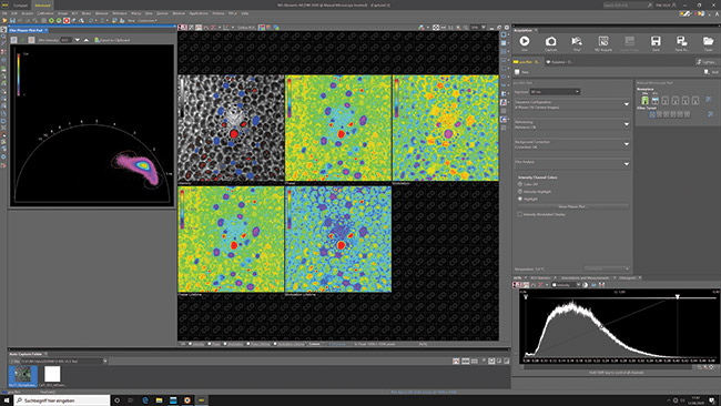
Figure 4. The Nikon NIS Elements AR microscope software, which shows an endogenous fluorescence measurement of a plant slice with all the result images of a frequency domain FLIM (FD-FLIM) measurement: normalized intensity, phase angle, modulation index, phase angle based lifetime and modulation index based lifetime (from left to right) and the phasor plot with its feedback to the intensity image (the corresponding pixels in the intensity image are false-colored with the elipse color). On the right side the pco.flim pad is visible. It allows to control all features of the pco.flim camera system.
FLIM workflow
A measurement of the lifetime distribution is made as follows:
1. Determination of the necessary excitation time for the sample to select an appropriate modulation frequency for the measurement.
2. Acquisition of a sequence of reference images that are subsequently transferred into computer memory. A sequence might comprise 2 × 2 frame pairs corresponding to the following phase positions: 0°-180° and 90°-270°, as well as 180°-0° and 270°-90°. The reacquisition of the frame pairs for reversed phase positions is necessary in order to minimize a remnant asymmetry in each pixel. An added benefit is that averaging in this way also improves the signal to noise. During this reference measurement a few measurements are done automatically to calibrate the image sensor.
3. Acquisition of an image sequence from the sample.
4. Immediate data processing of both sequences in the computer by the Nikon NIS Elements AR with pco.flim module software.
As an example, measurements were performed with human embryonal kidney cells (HEK-293) expressing a protein DJ-1 coupled with a FRET dye pair CFP/YFP (Figure 5). The expected lifetimes were in the range of 500 ps up to 3.5 ns, which could be resolved even though a suboptimum modulation frequency of 30 MHz was used. The total recording of the displayed image set took three seconds. Due to the fluorescence lifetime distribution it can be seen that the FRET efficiency in the nucleus of the cell was less compared to the value in the cytoplasma. FRET efficiency in so-called membrane sheets growing at the edge of the cells was larger. The measurements were done to compare the results with prior art, where identical results were achieved at a higher speed and better data quality5. Further, as a second example, the FLIM camera system was applied to measure the endogenous fluorescence lifetimes of a plant sample slice, lily of the valley, where different structures show significant variances in fluorescence lifetimes. This can be used to differentiate the plant structures or get additional information (Figure 6).
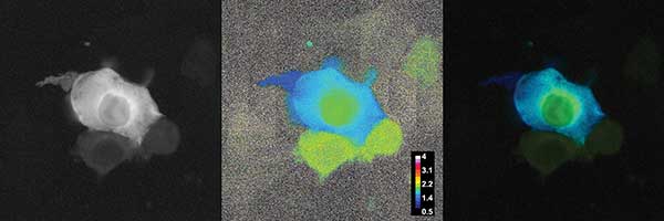
Figure 5. Förster resonance energy transfer (FRET) measurement of HEK-293 cells expressing a protein DJ-1 coupled with a FRET dye pair CFP/YFP (λexc = 447 nm, modulation = 30 MHz). The left image shows the fluorescence intensity of the measured cells. The middle image gives the phase angle based fluorescence lifetime distribution with a false color coding scaled from 500 ps to 4 ns. The right image shows the lifetime image weighted with the fluorescence intensity with the same false color coding. The weighting suppresses the noisy lifetime values. The differences in lifetimes are in the range of 800 ps to 1.7 ns. The differences between the nucleus, the cytoplasma, and the membrane sheet are clearly visible. Courtesy of F.S. Wouters and G. Bunt, University Medicine Göttingen.
As the modulation frequency can be set anywhere between 5 kHz and 40 MHz, multiple measurements can be performed — although for each frequency a useable reference with known decay, or at least with a significantly shorter decay, is required. Technical limitations in the sensor mean that a readout of each frame pair must be performed when the excitation light is off, and the necessary dark gate signal is generated within the camera system.
Figure 7 shows a pco.flim camera system mounted to a microscope. Two coaxial cables transmit modulation and dark gate signal to the laser diode module. If modulation frequencies above 20 MHz are required, for example if lifetimes in the range of a few nanoseconds have to be measured, laser diodes have to be applied. That makes the task to homogenously illuminate the view field of a microscope with laser light. To solve this issue and prevent the interference patterns called speckles, PCO also offers a pco.flim laser light source which guides the light with a typical liquid light guide that can directly be connected to the epi-fluorescence light input of the microscope to homogenously illuminate the sample.
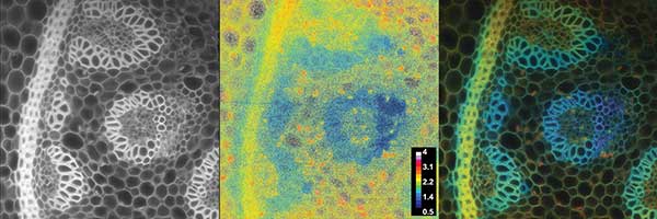
Figure 6. Endogenous fluorescence measurement of a lily of the valley slice sample (λexc = 447 nm, modulation = 30 MHz). The left image shows the fluorescence intensity. The middle image gives the phase angle based fluorescence lifetime distribution with a false color coding scaled from 500 ps to 4 ns. The right image shows the lifetime image weighted with the fluorescence intensity with the same false color coding. The weighting suppresses the noisy lifetime values. Courtesy of PCO AG.
Speed and precision
The first results with the new FLIM camera system in Figure 7 show that is possible to measure with excellent precision very fast luminescence lifetime images with a relatively simple setup at previously not achieved frame rates. This approach simplifies the process for specialists, opens up adoption of the technique for more routine studies, and will perhaps rejuvenate the field of fluorescence lifetime, as it were.
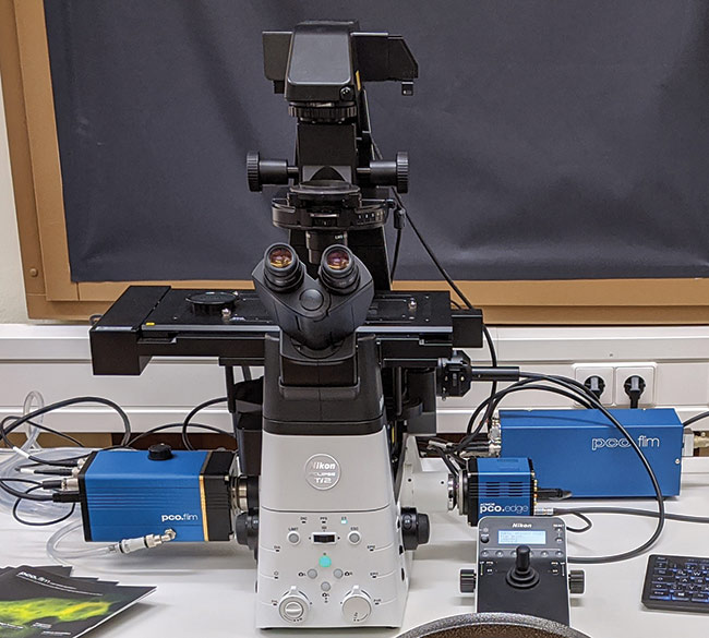
Figure 7. Basic microscope setup for FLIM with the new camera system, pco.flim. From left to right: the pco.flim camera system (PCO AG), an inverse Nikon fluorescence microscope (Nikon) and the pco.flim laser (PCO AG).
Meet the author
Gerhard Holst is the head of research at PCO AG in Kelheim, Germany; e-mail: [email protected].
Acknowledgment
This development has been enabled through support of the BMBF in association with projects 13N9242 and 13N11177. The author would like to thank Prof. F.S. Wouters-Bunt and Dr. G. Bunt for the excellent collaboration on the pco.flim applications.
References
1. G. Mariott et al. (1991). Time resolved imaging microscopy — phosphorescence and delayed fluorescence imaging. Biophys J, 60(6): pp. 1374-1387; J.R. Lakowicz, K.W. Berndt (1991) Lifetime-selective fluorescence imaging using an RF phase-sensitive camera. Review of Scientific Instrumentation, 62: pp. 1727–1734; T.W.J. Gadella Jr. et al. (1993). Fluorescence lifetime imaging microscopy (FLIM): spatial resolution of microstructures on the nanosecond time scale. Biophys Chem, 48: pp. 221-239.
2. M. Kühl et al. (2008). Imaging of oxygen dynamics within the endolithic algal community of the massive coral Porites lobata. J Phycol, 44: pp. 541-550.
3. A. Esposito et al. (2006). Innovating lifetime microscopy: a compact and simple tool for life sciences, screening and diagnostics, J Biomed, X11(3): 34016.
4. R. Franke and G.A. Holst. (2015). Frequency-domain fluorescence lifetime imaging system (pco.flim) based on a inpixel dual tap control CMOS image sensor. SPIE imaging, manipulation and analysis of biomolecules, cells and tissues XIII, at San Francisco. Vol. 9328.
5. S. Deeg et al. (2010). BAG1 restores formation of functional DJ-1 L166P dimers and DJ-1 chaperone activity. J Cell Biol, 188(4): pp. 505-513.