Admir Heljo, Precision Measurement Technologies
Time-to-digital converters provide highly accurate measurements for photonics applications – with less energy consumption and lower overall costs.
Measuring a quantity or value through digital monitoring of extremely small increments of time can provide significantly greater accuracy while also requiring substantially less current than other methods. Time-to-digital converters (TDCs) can directly measure the change of a quantity over time in exceedingly small increments, with accuracy in the picosecond range. The devices provide the advantages of direct digital data with adjustable resolution and operation modes for a broad range of photonics applications.
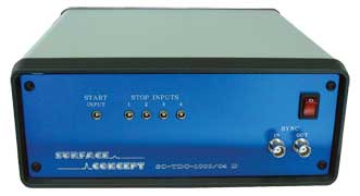
This time-to-digital converter instrument has four stop channels and is capable of resolution down to 27 ps.
TDCs are available in two basic forms, either as a complete device that can be applied to a broad range of measurement and testing applications, or as a chip that a designer can incorporate into custom designs to meet specific needs.
The TDC devices are compact, fast and user-friendly and are available with a variety of performance characteristics. Possible layouts include stand-alone housings and NIM modules (2/12). Generally, they are equipped with a high-speed USB 2.0 interface.
Typical applications include single-photon counting, mass spectrometry, optical system dynamic adjustment, UAV (unmanned aerial vehicle) terrain mapping, intrusion detection, measurement of laser pulse duration, and coincidence and fluorescence lifetime as well as a broad range of other time-of-flight (TOF) applications. Complete electronic measurement devices that employ TDC chips are readily available, so users such as universities and national laboratories can gain the benefits of this technology without having to design a custom system.
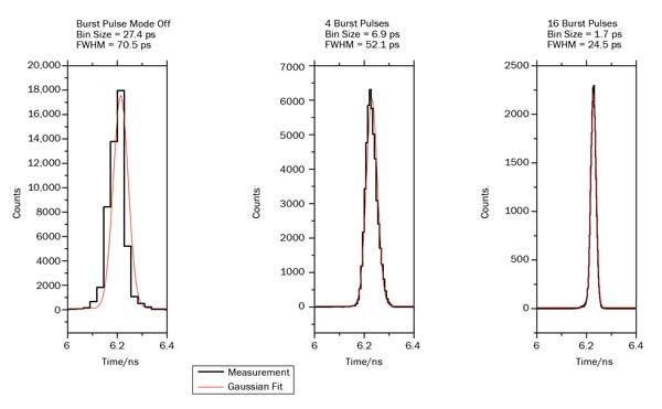
Time resolution results from a TDC instrument using burst mode, where each pulse is multiplied by hardware and is measured multiple times. FWHM = full width half maximum.
Mass spectrometry
For mass spectrometry applications, TDC chip technology uses time measurement to provide highly accurate results that also are more cost-effective than board-level systems or other solutions. Where speed in getting to a solution is critical, time can be saved by using an instrument-based device that incorporates TDC technology.
In mass spectrometry, ions are accelerated by an electric field of known strength, which results in all ions with the same charge having the same kinetic energy. The velocity of an ion depends on its mass-to-charge ratio. Once a particle is accelerated, the time it takes to reach a detector at a known distance (TOF) is measured. This time varies with a particle’s mass-to-charge ratio, since heavier particles reach lower speeds. Using this time value and related parameters, an ion’s mass-to-charge ratio can be determined.
By sorting the ions in a sample according to their mass-to-charge ratio and analyzing the resulting data, it is possible to identify unknown compounds, determine the composition and structure of a compound, quantify the amount of a compound in a sample, and study other physical, chemical or biological properties. Typical uses are as diverse as analyzing evidence from a crime scene to determining the level of contaminants in a water sample.
For OEM designers of mass spectrometry equipment and for laboratories building their own specialized equipment, selecting major components from a single source helps to ensure compatibility and achieve optimum performance. Companies offer a family of components tuned to work together, such as high-voltage power supplies, amplifiers and picosecond detectors as well as TDCs, to meet these needs. This system-level approach also saves development time, so the system is up and running more quickly.
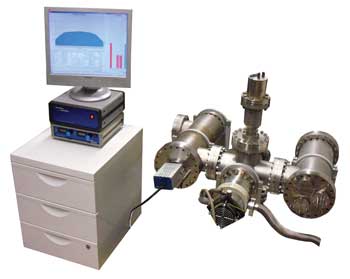
A delay line detector system including detector head, analog electronics, time-to-digital converter and high-voltage power supply.
Rangefinding
Rangefinding applications for TDC technology run the gamut from night vision to robotics. For designers developing commercial products, a TDC chip provides the greatest design flexibility. Laboratories performing experiments that incorporate or focus on rangefinding can specify an instrument-level TDC device that incorporates the same chip into a compact, fast and user-friendly device that is available with a variety of performance characteristics.
Rangefinding possibilities are almost infinite and vary from close range to long distance, the latter limited mainly by laser power and atmospheric variations. With this technology, the time it takes a laser beam to return from the moon could be measured. On the close-up side, practical applications include range-of-motion measurement for robotics as well as safety screens that define a hazardous area during operation. Other applications such as hunting scopes and military optics generally fall into the mid-range area.
Laser scanning of 3-D objects is still another area where the compactness and power efficiency of TDC solutions are
significant advantages. A scanner using this technology could be placed in the center of a room to map and create a 3-D model of that room. An entire building or other object could be mapped quickly and accurately.
On battery-powered portable devices such as hunting scopes or night-vision goggles and other military equipment, the accuracy, compact size and low power consumption of TDC circuits also provide major benefits. Costs compare favorably with other potential methods as well.
Single-photon counting
TDC technology provides a highly accurate way of determining the exact arrival time of a photon at a detector. Its low energy consumption also is an advantage, especially in applications such as scanners with multiple detectors. Lower power usage translates into cooler operating temperatures, minimizing the effect of temperature on detector operation.
Time-correlated single-photon counting is a technique used for fluorescence lifetime imaging. When a sample is excited by a laser, x-ray or other method, photons are emitted as it decays back to a ground state. Fluorescence lifetime describes the average time a fluorophore will remain in the excited stage before dropping back to the lower-level state. Fluorescence lifetimes typically are on the order of picoseconds to several nanoseconds, a range that is ideal for TDC measurement.
A common detector is the photomultiplier tube (PMT), but today many other solid-state detectors are available with even higher performance than the PMT. These faster lasers and detectors make it necessary to have electronics such as TDCs, which are capable of capturing and measuring these very short events.
When using TDC technology in single-photon counting applications, a constant fraction discriminator typically is applied before the signal enters the TDC to eliminate timing jitter.
Laser performance analysis
TDCs also find application in laser performance analysis to monitor production quality. Here, the instrument-level TDC can be used in the production environment to monitor the performance of completed laser assemblies prior to product shipment. In this application, laser parameters such as rise and fall times, along with laser pulse width measurement, can help to ensure compliance with product specifications. The instrument-level solution can be interfaced with a PC to log the performance for future reference, should the product be returned for repair or replacement.
Delay line detectors
Many applications that currently use either chip-level or instrument-level TDCs employ delay line detectors to capture position and timing information. The delay line detector offers true single-particle detection.
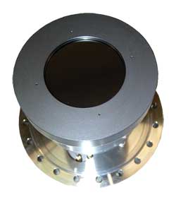
This large imaging delay line detector has time resolution.
Conceptually, this device is quite simple: A particle enters the delay line detector through a microchannel plate (MCP), which accelerates the particle. Below this MCP are two serpentine wires, one in the X direction and the other in the Y direction. When the particle strikes both the X and Y serpentine wires, an electrical pulse is created. The exact position of the strike can be determined by measuring the time differential between the arrival time at the X1 and X2 ports and the arrival time at the Y1 and Y2 ports.
These ports are usually amplified and run through a constant fraction discriminator to process the signals before they are applied to the inputs of either a chip-level TDC or an instrument-based solution. Either solution can provide high-resolution measurements of the position where the particle strikes. Additionally, the TOF information also can be delivered by either solution.
Standard delay line detectors are available with detector-area diameters ranging from around 30 mm on the low end to 80 mm or larger on the high end. Delay line detectors are a good match for the TDC technology because they are capable of very high count rates with very small dead times. Resolutions are in the 100-ps range because of the propagation times in the wire structures, even though the TDC itself can achieve higher resolutions.
When compared with other devices such as nonimaging MCP detectors, a phosphor screen with a CCD camera or single-channel electron multipliers, the delay line detector offers real single-event counting, time resolution and imaging capability, along with superior signal-to-noise ratio. Combinations like this are being used in applications that include electron microscopy, electron spectroscopy, electron diffraction, mass spectrometry, x-ray microscopy, electron imaging, UV imaging and a host of other applications.
Chip-based solutions
These TDC devices also are used to provide known quantities for testing custom systems designed around individual TDC chips. Such applications may include laser or night-vision rangefinding, intrusion detection, lidar and some coincidence measurement requirements, among others.
For such applications, where a designer wishes to tailor a measurement solution for specific needs or a new product design, the availability of individual TDC chips gives the designer the flexibility to customize each solution. Latest-generation chips feature multifunctional architecture designed for high single-shot resolution, best pulse-pair resolution and high measurement rates. Chips such as the ACAM GPX provide four operation modes, with up to eight channels and resolutions from 81 to 10 ps.
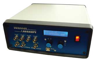
This pulse pattern generator has four individually programmed output channels with pulse periods down to 6.7 ns.
The availability of a chip-level TDC as well as a test instrument solution offers the most flexibility for the design engineer or scientist. For those designing a product from the ground up, the chip-level solution allows for the most creative design possibilities. With the chip-level solution, you can be more creative with the product packaging because you design the assembly to fit the package.
For those designing complex systems, the instrument-level solution offers good flexibility without the need to develop each piece of the system yourself. For complex systems, the availability of blocks such as delay line detectors, amplifiers, constant fraction discriminators, logic fan-outs and other system pieces makes it easier to assemble complex systems. These various system blocks can even be integrated to deliver a higher-level system approach to design.
Meet the author
Admir Heljo is a product application specialist at Precision Measurement Technologies in Clearwater, Fla.; email: [email protected].