Pu Zeng, Shuang Liu, Guanglu Wei, Shangjian Zhang and Yong Liu, University of Electronic Science and Technology of China; and Charles M. Falco, University of Arizona
Researchers investigate the principle of loss cancellation in proposing a configuration of lossless microring filters fabricated on Er3+/Yb3+-co-doped phosphate glass and using ion-exchanged techniques. The optical round-trip length and the coupling coefficient are optimized to provide the best performance. The numerical simulation results show that the free spectrum range (FSR) can reach 0.24 nm when the optical round-trip length (L) is no less than 10 mm.
With better understanding and improved fabrication technology, ring resonator filters are now widely used in optical communications devices including switches, amplifiers, attenuators and
routers. Ring resonator structures have been a focus of interest in recent years,
and the integrated waveguide microring resonator is especially useful because of
its compact size and ease of integration. However, because of its great loss factor,
it cannot be used in some applications.
The problem is attributed mainly to the loss in waveguide propagation
and bend: Propagation loss in the waveguide is dominated by scattering, which can
be reduced by better fabrication technology and sidewall smoothing processes; bend
loss can be substantially reduced by using sufficiently large bend radius waveguides
– but this adds bulk.
Minimizing ring size as much as possible – without introducing
significant bend loss – helps achieve a high packaging density of optical
components. A number of tested strategies exist for reducing bend loss. Increasing
the relative index difference between the core and the cladding of a waveguide allows
tighter low-loss bends. Some researchers have proposed other approaches1 or have
suggested using UV irradiation of the core.2
Er3+/Yb3+-co-doped phosphate glass is a waveguide amplifier. Er3+-doped amplifiers also are widely used. But it is preferable to employ Er3+/Yb3+-co-doped phosphate glass because the presence of Yb3+ can eliminate the Er3+ ion-ion interactions
and increase pump efficiency, which can create higher gain. The high gain of Er3+/Yb3+-co-doped phosphate glass can compensate for great loss in the microring.
We propose an integrated optical waveguide ring resonator filter
in which the ring resonator structure is fabricated on Er3+/Yb3+-co-doped phosphate glass using ion-exchanged techniques. Figure 1 is the structure of an integrated
optical waveguide ring resonator filter on Er3+/Yb3+-co-doped phosphate glass, and Figure 2 is the cross section of an Er3+/Yb3+-co-doped waveguide.
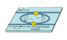
Figure 1. Schematic of an integrated optical waveguide ring resonator filter.
With Er3+/Yb3+-co-doped phosphate as the substrate, this approach
uses ion-exchange techniques to fabricate the integrated waveguide ring resonator
filter, rendering a theoretical assessment of the filter characteristics and providing
a new way to design a lossless ring filter. Adopting the active ring resonator with
amplifying medium as a substitute for the passive ring resonator can greatly compensate
for loss, allowing the filter to achieve an “ideal-losses” state and,
therefore, very good fineness; at the same time, there is no need to introduce any
sophisticated loss cancellation processes. Also, the filter can be made compact
and its inner gain controlled easily by changing the pump power. Promising applications
for this filter include optical add/drop modules, spectrum equalization and narrow
spectrum sources.
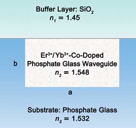
Figure 2. Cross section of integrated waveguide ring resonator filter.
Loss cancellation
As shown in Figure 1, part of the incidental light (E1) with different
wavelengths λ1, λ2 to λn is coupled into the ring (E2) by the coupler (C2); only those wavelengths λx that satisfy

can pass through the ring resonator (E3). The transmitted light
(E3) suffers great loss in the straight waveguides and the circulation. The propagation loss, as analyzed in the second paragraph, can be reduced by better fabrication
technology and sidewall smoothing processes. Through these processes, propagation
loss can be controlled below 0.01 dB/mm – negligible compared with bend loss.
The bend loss changes with bend radius and the waveguide dimension, both of which
dramatically affect the filter performance. The normal dimension of a waveguide
made by ion-exchanged techniques is usually about 5 to 7 μm wide (a) and 4
to 7 μm deep (b), as shown in Figure 2. The WKB3 and Marcatili4 methods are two popular ways to estimate the bend loss; here, n1 = 1.45, n2 = 1.548, n3 = 1.532, a = 5 μm, b = 6 μm – the bend loss versus bend radius figure calculated based on the two methods shown in Figure 3.
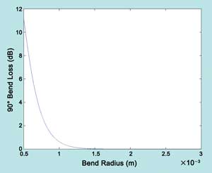
Figure 3. Bend loss versus bend radius.
A theoretical gain of 0.413 dB/mm is reported,5 and recent progress
has led to a gain of more than 0.3 dB/mm6,7; Figure 3 shows that, if the bend radius
is >1 mm, the bend loss is <0.3 dB/mm, which means that, when the concentrations
of Er3+ and Yb3+ are properly controlled, the gain can compensate the round-trip loss. For communications systems, ideal lossless filters are highly desirable. To
this end, Er3+/Yb3+-co-doped waveguides are used.
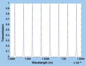
Figure 4. Transmission spectrum of the filter (K = 0.1, L = 9.72 mm).
Filter characteristics
Many factors affect the characteristics of the ring resonator
filter, including coupling coefficient (K), coupler loss, optical round-trip length
(L), round-trip loss, fineness and FSR. If the coupler loss is neglected, all the
factors are related to K and L. Therefore, all the changes of characteristics can
be calculated from K and L.
The spectrum width:
(Equation 1) 
where the speed of light c = 299,792,458 m/s, and
(Equation 2) 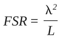
By increasing the reflectivity R or optical length L, narrower Δ1/2 can be obtained. And FSR decreases as L increases. Two situations (1) K1 = K2, (2) K1 ? K2 also must be considered. (K1 and K2 are the coupling coefficients of the couplers C1 and C2.)
1. K1 = K2
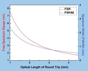
Figure 5. FSR versus L and full width half maximum (FWHM) versus L.
Figure 4 is the transmission spectrum of the filter when K1 = K2 = 0.1, L = 9.72 mm. Figure 5 is FSR versus L and full width half maximum (FWHM) versus L. Clearly, the FSR and spectrum width become smaller as L increases.
Therefore, by changing the round-trip length L, a different FSR and spectrum width can be obtained. But this is the situation when K1 = K2 (in application, sometimes the coupling coefficient K1 ≠ K2).
2. K1 ≠ K2
The ring resonator and the Fabry-Perot etalon share the same theory
(multibeam interference) as illustrated in Figure 6. This can be considered as the
situation r1 ≠ r2 ≠ r3, and the reflected field is calculated as follows:
(Equation 3) 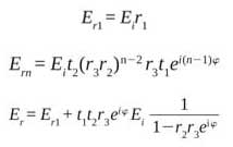
The ratio of reflected field to incidental field is:
(Equation 4) 
where
Equation 5) 
Then
(Equation 6) 
Figure 7 is the transmission spectrum with different coupler coefficients;
clearly, the transmission reaches 1 when K1 = K2. And if there is a difference between K1 and K2, the transmission power decreases. Therefore, if K1 ≠ K2, the transmission power suffers considerable loss, and the loss increases as the difference between K1 and K2 increases. Thus, to achieve better filter performance, the coupling coefficient K1 should equal K2.
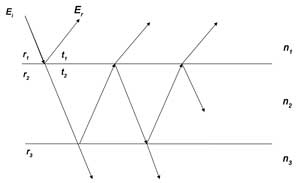
Figure 6. Multibeam interference in Fabry-Perot etalon (r1 is the reflection coefficient from air into the cavity; r2 is the reflection coefficient from the cavity into the upper surface; and r3
is the reflection coefficient from the cavity into the lower surface.
The transmission coefficient from the cavity into the upper surface is t1, and the transmission coefficient from air into the upper surface is t2. Ei is incidental light, and Er is reflected light).
Considering that the input center wavelength is 1550 nm, and, according to the numerical simulation, the FSR is about 0.1 ~1 nm, we usually need greater FSR. But as the FSR increases, the round-trip length decreases (FSR = λ2/L); and as seen in Figure 3, the bend loss of the ring sharply increases. So, according to the analysis above, we set the bend radius as 1 mm; namely, optical round-trip length L = 9.72 mm, FSR = 0.24 nm. Then, according to the numerical simulation, Δλ1/2 should be <0.12 nm,
(Equation 7) 
According to Equation 1:
(Equation 8) 
So the optimal optical round-trip length is L = 9.72 mm; to get narrower pulses, we set the coupling coefficient K1 = K2 = 0.1.
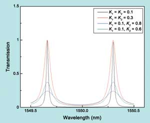
Figure 7. Transmission spectrum with various coupler coefficients.
An ideal lossless ring filter can be fabricated on Er3+/Yb3+-co-doped
phosphate glass using ion-exchanged techniques to produce ideal loss cancellation.
We have theoretically analyzed and simulated the characteristics of the filter and
found that, when the optical round-trip length L is no less than 10 mm, the filter
achieves an ideal lossless state, and an FSR of 0.24 nm is obtained. The numerical
simulation is based on an ideal model, considering the coupler is lossless.
Meet the authors
Pu Zeng, Shuang Liu, Guanglu Wei, Shangjian Zhang and Yong Liu
work in the School of Optoelectronic Information at the University of Electronic
Science and Technology of China in Chengdu. Charles M. Falco is a professor at the
College of Optical Sciences at the University of Arizona in Tucson. To contact the
authors, e-mail: [email protected].
Acknowledgments
This project was supported in part by the Outstanding Youth Scientific
Foundation of China (60925019), the Youth Scientific Foundation of China (60907008),
the Fundamental Research Funds for the Central Universities (ZYGX2009X010) and the
CCD Research Center of China Electronics Technology Group Corp.
References
1. E.G. Neumann and W. Richter (1983). Sharp bends with low losses
in dielectric optical waveguides. Appl Opt, Vol. 22, Issue 7, pp. 1016-1022.
2. R.A. Jarvis et al (1997). Bend-radius reduction in planar waveguides
using UV post-tuning. Electr Lett, Vol. 33, Issue 10, pp. 891-894.
3. W. Berglund and A. Gopinath (2000). WKB analysis of bend losses
in optical waveguides. Journ Lightwave Tech, Vol. 18, Issue 18, pp. 1161-1166.
4. E.A. Marcatili (1969). Dielectric rectangular waveguides and
directional coupler for integrated optics. Bell Syst Tech Journ, Vol. 48, Issue
21, pp. 2071-2102.
5. A. Shooshtari et al (1998). Yb3+ sensitized Er3+-doped waveguide
amplifiers: A theoretical approach. Opt and Quantum Electr, Vol. 30, Issue 4, pp.
249-264.
6. S.H. Xu et al (2007). Er3+/Yb3+ co-doped phosphate glass fibre
with gain per unit length greater than 3.0 dB/cm. Chin Phys Lett, Vol. 24, Issue
7, pp. 1955-1957.
7. V. Donzella et al (2010). Ion-exchanged Er3+/Yb3+ co-doped
waveguide amplifiers longitudinally pumped by broad area lasers. Opt Expr, Vol.
18, Issue 12, pp. 12690-12701.