Dr. Jonathan S. Steckel, Dr. John Ho and Dr. Seth Coe-Sullivan, QD Vision Inc.
Large color gamut and better color reproducibility will be highly desired features of displays in the near future. Quantum dots will be the down-conversion technology of choice, allowing LCD makers to cost-effectively reach and exceed 100 percent of the NTSC and Adobe RGB color standards while achieving maximum system efficiency.
Thin-film transistor liquid crystal displays (LCDs) have undisputedly become the dominant flat panel display technology,1 with annual shipments of billions of units. LCDs provide the visual interface between humans and electronics in applications ranging from smartphones, tablets and computers to large-screen TVs. Prior shortcomings – including limited viewing angle, poor contrast ratio, high power consumption and slow response times – have been addressed and are now no longer major concerns with the technology. The remaining technical areas receiving attention are motion-picture image blurring of LCD displays at lower temperatures due to the slow response time of the liquid crystals,2–4 improved image contrast ratio using adaptive dimming control5 and wider color gamuts enabling accurate color reproducibility.6–8
The LCD backlight is transmitted through the color filter array (CFA) in the LCD panel, which determines the size of the color gamut and therefore the range of colors the display can render. Based on detailed investigations,8 we now have a good understanding of the fundamental trade-off between color gamut and system efficiency and how best to address both in thin-film transistor LCDs.
Recently, white LEDs (WLEDs) have rapidly replaced cold cathode fluorescent lamps as the backlight source in LCDs, because LEDs enable thinner display form factors, wider color gamut, higher brightness and lower power consumption.9–11 The most common WLED currently used in LCD displays is a blue-emitting InGaN LED die that excites a yellow-emitting down-converting phosphor (Ce:YAG). The Ce:YAG phosphor sits directly on the LED die, dispersed in a silicone-based polymer, creating efficient and cost-effective light for the display. However, because of the phosphor’s broad yellow emission spectrum (>100-nm full width half maximum [FWHM]), the color gamut is quite poor and able to achieve only ~70 percent coverage of the NTSC standard (National Television Standard Committee [CIE 1931]) and ~50 percent coverage of the new Rec. 2020 standard (proposed UHDTV color space) at reasonable system efficiencies.
Several types of red- and green-emitting phosphors12 have been recently reformulated for narrower-band emission compared with Ce:YAG and now increase the color gamut to ~80 percent coverage of NTSC (~60 percent coverage of Rec. 2020) at reasonable system efficiencies. Although it is possible that narrowband red- and green-emitting phosphor technology will continue to improve over the next several years and be applied more heavily to LCD displays, it is a mature technology that may be reaching practical limits. Colloidal semiconductor nanocrystals, or quantum dots (QDs), on the other hand, represent a relatively new display technology that is demonstrating significant and fundamental advantages over sulfide-13 and nitride14-based narrowband red- and green-emitting phosphors.
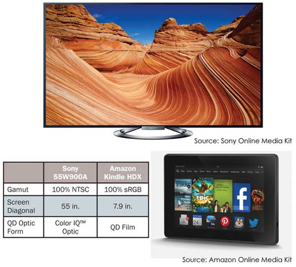
Figure 1. Images of a commercially available TV and a tablet, both using quantum dots to produce wider color gamuts. The inset table highlights key display information.
The exceptional quality of QD materials and the degree of control over their important optical properties at large scales have allowed the launch of the first mainstream QD-enhanced consumer electronic products in 2013.15 Sony Bravia Triluminos TVs, containing QD Vision’s Color IQ optics, were first announced at the 2013 Consumer Electronics Show.17 Several different TV models are now available, all with a color gamut of ~100 percent NTSC (CIE 1931) area. Nanosys and 3M also have successfully launched a mainstream QD-enhanced display product: the Amazon Kindle Fire HDX 7.9-in. tablet.18 Figure 1 shows examples of these two QD-enhanced LCD displays. The benefits of using QDs as the down-conversion material for LCD displays are numerous, and many prominent analysts are now forecasting that most wide-color-gamut LCD displays will be QD-enabled over the next several years.
Figure 2 shows the three main architectures for incorporating QDs into an LCD display, two of which (edge optic and film) are currently being used in the tablet and TV products shown in Figure 1. In the third mode of operation, shown in Figure 2, the QDs reside directly on the LED chip. This is a desirable format because less QD material is required per display, and ease of system integration is maximized. However, this is also the most demanding format, requiring the QDs to withstand higher temperatures and excitation fluxes when compared with edge optic and film – and, therefore, it will require more development at this point in time. Many companies are working hard to develop QD material systems that will enable on-chip implementation in the near future.
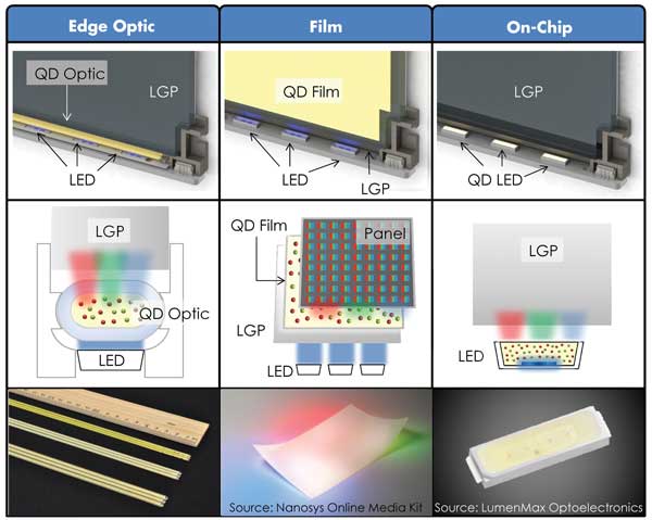
Figure 2. 3-D, 2-D and photographic images of three different QD form factors for enhancing color saturation in display backlights: edge optic, film and on-chip (the on-chip photo is a WLED product representative of a QD-LED form factor). Note that the blue LED light source and the various placements of the QDs in the system affect operating optical flux and temperature conditions. LGP = lightguide plate.
Organic light-emitting devices (OLEDs) are continuing to gain market traction in small displays and now are also available in limited supply in larger sizes due to some advantages over LCDs, including color gamut, contrast and thinner form factor.19 However, yield, cost and availability will likely limit market penetration of OLED technology for many years. Also, recent and continued advancements in LCD technology – coupled with new and emerging BLU technologies such as QD-containing LCD-BLU – are allowing LCD displays to close the gap with OLEDs in most of these performance areas, slowing down OLED market adoption. Currently, QD-enhanced LCD displays can achieve color-gamut performance that is better than that of OLED TVs, while utilizing the mature and highly cost-efficient LCD infrastructure.
Color tunability
Colloidally grown QDs for displays comprise a semiconductor core (1-10 nm in diameter), a wider-bandgap semiconductor shell and a coating of organic passivating ligands.20 The solution growth techniques developed over the past 20 years now enable separate control and tuning of the physical composition and properties of the core, shell and ligand materials. Because of the quantum confinement effect,21 the physical size, shape and composition of the core and shell determine the wavelength of light the particles emit. This allows reproducible tuning of the emission center wavelength to within ±1 nm of a color wavelength target anywhere across the entire visible spectrum.
This is a property unique to QDs and a large technical advantage over phosphors. When this tuning ability is translated into CIE X,Y coordinate space and plotted at 1-nm increments on the CIE chromaticity diagram, the curves shown in Figure 3 are obtained. Such precise, tunable color allows display makers to accurately adjust the display gamut area and overlap with a specific standard (e.g., NTSC or Adobe RGB) while keeping system efficiency as high as possible. This is critical, because displays and panels of various sizes made by different manufacturers can have dissimilar CFAs, light-management architectures and materials that greatly influence how much light and which wavelengths from the BLU make it through the panel to the viewer.
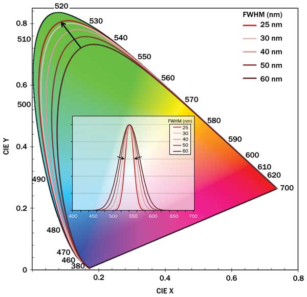
Figure 3. As FWHM of the quantum dot narrows from 60 to 25 nm (see inset), the simulated spectral locus gets pushed closer to the edge of the CIE diagram. Simulations assume a Gaussian QD emission profile.
Color purity
The QD particle size and shape uniformity determine the emission peak width, defined as the FWHM. High size and shape uniformity is now achievable through careful control of QD synthesis conditions, resulting in emitters with extremely narrow linewidths. Recent generations of QDs have linewidths below 30 nm in the red and green.
The large-scale, rapid-injection batch synthesis method from QD Vision provides QD solutions containing >1019 particles that are all within approximately ±1 atomic length of each other. This translates into extremely small batch-to-batch variation (±1-2 nm) from the mean center wavelength of emission and the FWHM.16 To restate this manufacturing control as it relates to displays, Figure 4 shows the photoluminescence (PL) emission data for over 50 red and green QD batches converted into u′,v′ color space and plotted on the CIE 1976 u′,v′ Uniform Chromaticity Diagram. The accuracy of the colors can then be compared to the eye’s sensitivity to color, where 1 JNCD (just-noticeable color difference) = Δ (u′,v′) = 0.004 on the CIE 1976 Uniform Chromaticity Scale.
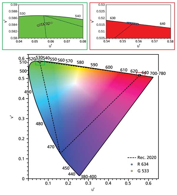
Figure 4. Quantum dot PL emission data of more than 100 consecutive large-scale batches plotted on the 1976 CIE Uniform Chromaticity diagram (u′,v′ color space) demonstrating routine batch-to-batch variance in color (peak wavelength [PWL] and FWHM). Each point represents one batch. Inset graphs show zoomed-in portions of the CIE diagram to indicate additional detail. Based on simulations, a possible red QD PWL/FWHM target is 634/27 nm, and a possible green target is 533/35 nm. 100 percent of red QD batches and 94 percent of green QD batches are within ±1 JNCD (just-noticeable color difference), equivalent to ?u′,v′of 0.0040. Two colors that have a JNCD of less than 3 are visually indistinguishable.
JNCDs offer a precise and objective way to evaluate the color accuracy of a display in terms of the eye’s sensitivity to color. Typically, color errors less than 3 JNCDs are considered visually indistinguishable from perfect. When the calculated Δ u′,v′numbers are converted to JNCDs, 100 percent of the red QD batches and 94 percent of the green batches are ±1 JNCD away from the average (u′,v′), and 100 percent of both are ±3 JNCDs away from the average (u′,v′).
QD vs. phosphor color performance
Publicly available scientific data indicates that a number of narrowband red- and green-emitting phosphors are relevant and attractive for achieving wider-color-gamut LCD displays (80 to 85 percent NTSC [CIE 1931]), compared with Ce:YAG (~70% percent NTSC [CIE 1931]): K2SiF6:Mn,22 SrLiAl3N4:Eu,23 SCASN:Eu,24 CaS:Eu,25, 26 β-SiAlON:Eu27-29 and SrGa2S4:Eu.25,30 Table 1 shows select display-relevant optical performance properties of these narrowband phosphors, relative to QDs. Currently, the FWHM of phosphors can be as narrow as 40 to 50 nm in the green and 55 to 65 nm in the red, but the possible spectral tuning range is very limited.22-30 Figure 3 illustrates how much area in the CIE diagram can be covered by a given visible light emitter when varying the linewidth from 60- to 25-nm FWHM. As the emission peak narrows, significantly more of the visible color space can be covered. At operating conditions (temperatures >50 °C), a reasonable QD FWHM for a commercially viable LCD display product in the next one to two years is ~25 nm in the red and the green.
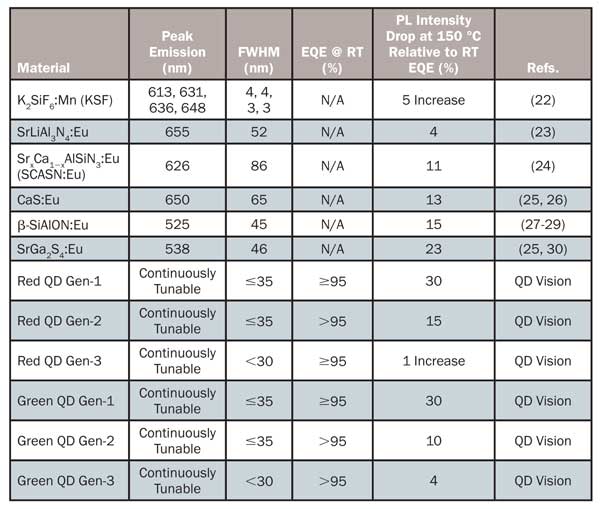
Table 1. Examples of red- and green-emitting narrowband phosphors with some of their display-relevant optical performance properties found in publicly available scientific data. External quantum efficiency (EQE) data at room temperature (RT) is not consistently reported in the literature for the phosphors and is therefore not included here. Red and green Generations 1, 2 and 3 QD optical properties are shown for comparison. PL = photoluminescence.
Precise tunability in the center wavelength of emission, coupled with the very narrow peak linewidth of QDs, translates directly into ultrawide color gamuts. Figure 5 shows this by plotting the color-gamut triangles on the CIE chromaticity diagram of simulated 25-nm FWHM QDs, compared to the best red (SrLiAl3N4:Eu; ~52-nm FWHM) and green (β-SiAlON:Eu; ~45-nm FWHM) phosphor combination based on available PL spectra from the technical literature. Gamut simulations used different combinations of the four red-emitting phosphors and two green-emitting phosphors, resulting in a range of Rec. 2020 overlap of 67 to 77 percent. Two different CFAs were used for each combination, illustrating how important CFA selection is to final display gamut area and overlap for a given standard. Using a narrowband CFA (CFA2) combined with simulated 25-nm-FWHM-emitting red and green QDs, the emission bands can be well separated from one another, and color gamuts of >120 percent NTSC (CIE 1931) area and >90 percent Rec. 2020 area and overlap are achievable. The Rec. 2020 gamut standard is becoming the new benchmark for UHD display color performance, and QDs are currently the only LCD technology that can cost-effectively achieve >90 percent coverage with the highest system efficiency.
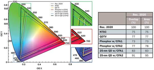
Figure 5. Phosphor and QD (simulated 25-nm FWHM) primaries plotted against Rec. 2020 and NTSC reference gamut triangles. The QD TV is the 55W900A TV from Sony. The phosphor referenced is a combination of the red phosphor SrLiAl3N4:Eu (~52-nm FWHM)23 and green phosphor β-SiAlON:Eu (~45-nm FWHM)28 taken from available PL spectra from the technical literature. CFA1 and CFA2 are two different commercially available color filter arrays, showing the impact that different color filter transmission profiles can have on achievable color gamut.
In the LCD monitor space, a need also exists to achieve 100 percent Adobe RGB color performance at better cost and system efficiency. QD emission wavelengths can be tuned to match the Adobe RGB green point exactly (same green point as the NTSC standard in Figure 5) for any CFA. Other BLU solutions, including narrowband phosphors, miss the green point and cannot reach 100 percent Adobe RGB overlap. QDs are therefore uniquely suited to allow LCD manufacturers to achieve full-gamut Adobe RGB color performance at the highest system efficiency and lowest cost.
Display efficiency: QDs vs. phosphors
Table 2 shows LCD system simulation results of the relative efficiency to WLEDs and the color gamut of 25-nm-FWHM red- and green-emitting QDs versus narrowband phosphors used as light sources in the BLU. The two phosphors used in the simulation were the same as those shown in Figure 5: SrLiAl3N4:Eu and β-SiAlON:Eu. When the 25-nm FWHM red QD peak is tuned to 617 nm and the green to 531 nm, the area and overlap relative to Rec. 2020 are the same as those of the phosphors, but the phosphors’ relative efficiency to WLED is half that of the QDs.
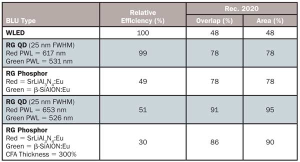
Table 2. LCD simulation results comparing the Rec. 2020 color gamut results and the relative efficiency to WLED of 25-nm FWHM red- and green-emitting QDs at different wavelengths of emission versus red- and green-emitting narrowband phosphors. The blue LED spectrum used in these simulations had a peak wavelength (PWL) of 444 nm and a FWHM of 19 nm.
For both QDs and phosphors, as the color gamut increases, the efficiency relative to WLED decreases. In the case of phosphors, the gamut is improved by increasing the thickness of the CFA by 300 percent. This gives a 70 percent less efficient solution with a reduced gamut compared with the QDs, where the red peak wavelength is tuned out to 653 nm and the green to 526 nm, giving an extremely large color gamut (91 percent overlap and 95 percent area of Rec. 2020) with an efficiency of 51 percent relative to WLED. The red and green QD wavelengths in this simulation were achieved by tuning to wavelengths that maximized the overlap and area of the color gamut. The fundamental trade-off in system efficiency with increasing color gamut arises because, as the red, green and blue emission bands move farther from 555 nm (peak photopic response), their contribution to system brightness is reduced.8, 25
Material efficiency: QDs vs. phosphors
Separately engineering the semiconductor core, shell and ligand composition using colloidal chemistry maximizes the efficiency of QD materials in the solid state and increases their efficiency at temperatures and fluxes relevant to LCD displays. Using a CdSe core and a shell made up of Cd, Zn and S, we have achieved solid-state emission efficiencies (external quantum efficiency, or EQE) of >95 percent in the red and green wavelength regions at scale. In addition, we have directly addressed temperature stability of the emission efficiency by focusing on QD exciton confinement and maximizing the conduction and valence band offsets of the shell band energies relative to core band energies.
Advancing the QD shell synthesis process results in QD materials that can maintain solid-state efficiencies of >95 percent at temperatures as high as 150 °C. Table 1 shows the PL intensity changes as a function of temperature for three generations of red and green QD materials, relative to the four red and two green narrowband phosphors discussed above. For both red and green emitters, QDs can match or exceed the efficiency at 150 °C of narrowband phosphors.
Carefully engineering the QD structure modifies the thermal quenching behavior from Generation 1 to 3 in both the red and the green. This is a feat that narrowband red- and green-emitting phosphors cannot yet claim due to certain physical limitations.
Meet the authors
Dr. Jonathan S. Steckel is a founder of QD Vision Inc. in Lexington, Mass.; email: [email protected]. Dr. Seth Coe-Sullivan is a founder and a member of the board of directors, as well as its chief technology officer; email: [email protected]. Dr. John Ho is QD Vision’s advanced development manager; email: [email protected].
References
1. M. Schadt (2009). Milestone in the history of field-effect liquid crystal displays and materials. Jpn J Appl Phys, Vol. 48, No. 3S2, p. 03B001.
2. H. Kikuchi et al (2002). Polymer-stabilized liquid crystal blue phases. Nat Mater, Vol. 1, Issue 1, pp. 64-68.
3. K.M. Chen et al (2010). Submillisecond graylevel response time of a polymer-stabilized blue-phase liquid crystal. J Display Technol, Vol. 6, Issue 2, pp. 49-51.
4. Y. Chen et al (2011). A microsecond-response polymer-stabilized blue phase liquid crystal. Appl Phys Lett, Vol. 99, Issue 20, p. 201105.
5. D. Cho et al (2011). A novel adaptive dimming LED backlight system with current compensated X-Y channel drivers for LCD TVs. J Display Technol, Vol. 7, Issue 1, pp. 29-35.
6. M. Anandan (2008). Progress of LED backlights for LCDs. J Soc Inf Disp, Vol. 16, Issue 2, pp. 287-310.
7. G. Harbers et al (2007). Performance of high power light emitting diodes in display illumination applications. J Display Technol, Vol. 3, Issue 2, pp. 98-109.
8. Z. Luo et al (2013). Wide color gamut LCD with a quantum dot backlight. Optics Express, Vol. 21, Issue 22, pp. 26269-26284.
9. M. Anandan (2008). Progress of LED backlights for LCDs. J Soc Inf Disp, Vol. 16, Issue 2, pp. 287-310.
10. G. Harbers et al (2007). Performance of high power light emitting diodes in display illumination applications. J Display Technol, Vol. 3, Issue 2, pp. 98-109.
11. R. Lu et al (2008). LED-lit LCD TVs. Mol Cryst Liq Cryst, Vol. 488, Issue 1, pp. 246-259.
12. C.C. Lin and R.-S. Liu (2011). Advances in phosphors for light-emitting diodes. J Phys Chem Lett, Vol. 2, Issue 11, pp. 1268-1277.
13. S. Neeraj et al (2004). Novel red phosphors for solid-state lighting: The system NaM(WO4)2−x(MoO4)x:Eu3+ (M=Gd, Y, Bi). Chem Phys Lett, Vol. 387, Issues 1-3, pp. 2-6.
14. R.-J. Xie et al (2007). 2-phosphor-converted white light-emitting diodes using oxynitride/nitride phosphors. Appl Phys Lett, Vol. 90, Issue 19, p. 191101.
15. K. Bourzac (Jan. 17, 2013). Quantum dots go on display: Adoption by TV makers could expand the market for light-emitting nanocrystals. Nature, Vol. 493, No. 7432, p. 283.
16. J.S. Steckel et al (2013). Quantum dot manufacturing requirements for the high volume LCD market. SID Symposium Digest of Technical Papers, Vol. 44, Issue 1, pp. 943-945.
17. http://www.qdvision.com/content1566.
18. E. Shum and R. Steele (December 2013). SIL 2014 sets its sights on SSL evolution in global markets. LEDs Magazine, p. 27.
19. D. Barnes (2013). LCD or OLED, who wins? SID Symposium Digest of Technical Papers, Vol. 44, Issue 1, pp. 26-27.
20. B.O. Dabbousi et al (1997). (CdSe)ZnS core-shell quantum dots: Synthesis and characterization of a size series of highly luminescent nanocrystallites. J Phys Chem B, Vol. 101, Issue 46, pp. 9463-9475.
21. L.E. Brus (1983). A simple model for the ionization potential, electron affinity, and aqueous redox potentials of small semiconductor crystallites. J Chem Phys, Vol. 79, Issue 11, pp. 5566-5571.
22. T. Ishiwata, M. Watanabe and K. Nishimura. Phosphor Composition for a Luminaire. EP 2642519 A2.
23. P.J. Schmidt et al. New Phosphors, Such as New Narrow-Band Red Emitting Phosphors, for Solid State Lighting. WO2013175336 (A1).
24. Y.-S. Kim et al (2013). Red-emitting (Sr,Ca)AlSiN3:Eu2+ phosphors synthesized by spark plasma sintering. ECS J Solid State Sci Technol, Vol. 2, Issue 2, pp. R3021-R3025.
25. Y. Ito et al (2013). A backlight system with a phosphor sheet providing both wider color gamut and higher efficiency. SID Symposium Digest of Technical Papers, Vol. 44, Issue 1, pp. 816-819.
26. K. Swiatek et al (1993). Optical recombination mechanisms in Eu2+-doped CaS and SrS thin films. J Appl Phys, Vol. 74, Issue 5, pp. 3442-3446.
27. D.-H. Kim et al (2011). Light emitting properties of SiAlON:Eu2+ green phosphor. Applied Physics A, Vol. 102, Issue 1, pp. 79-83.
28. K. Takahashi et al (2011). Toward higher color purity and narrower emission band β-sialon:Eu2+ by reducing the oxygen concentration. Electrochem and Solid-State Lett, Vol. 14, Issue 11, pp. E38-E40.
29. K. Takahashi et al (2012). On the origin of fine structure in the photoluminescence spectra of the β-sialon:Eu2+ green phosphor. Sci Technol Adv Mater, Vol. 13, No. 1, 015004.
30. C. Chartier et al (2005). Photoluminescence of Eu2+ in SrGa2S4. J Lumin, Vol. 111, Issue 3, pp. 147-158.