Joel S. Silfies, Nikon Instruments Inc.
Ever since Dutch
scientist Antonie van Leeuwenhoek first described the cellular world in the 1660s,
the disciplines of biology and physics have been pushing each other to design better
tools and methods for exploring the microscopic living world. Cutting-edge questions
posed by biologists push designers, engineers and physicists to discover and design
new microscopy tools to explore biological questions. New microscopy tools and techniques
allow biologists to ask questions that previously were impossible to answer.
This article will explore some of the innovative microscopy tools
that allow today’s researchers to image faster, to observe for longer time
periods while maintaining cell viability, and to resolve structures that, just a
few years ago, were totally out of the reach of light microscopes.
New challenges in microscopy have emerged as biological researchers
move from observation of fixed tissues or single images of living cultures to the
study of cell behavior over time. One of the most difficult challenges is thermal
“drift” at the sample plane. To achieve the best possible images and,
thus, quality data, the sample must stay in focus for the duration of the experiment.
This requires that the living cells maintain a constant distance from the front
of the microscope objective lens. With high-magnification and high-resolution objectives,
movement of as little as 0.25 to 0.5 µm of Z displacement can cause the sample to
be completely out of focus, producing useless data. This can be caused by <1
°C of shift in temperature.
Such thermal drift is common. Sample vessel, immersion and sample
media, and cells themselves are all prone to thermal expansion or contraction with
fractions-of-a-degree change in ambient temperature. Other sources are sample incubation
and the addition of drugs or perfusing materials into the sample, both of which
can set up thermal gradients and lead to almost constant drift.
If a reference point in the system could be established and tracked,
a system could be created to eliminate thermal drift’s impact. Luckily, when
working with adherent cells, the coverslip of the sample vessel can serve as a reference
point. Recently developed commercial systems such as Nikon Instruments’ Perfect
Focus System (PFS) use the principle that, when an illumination source transitions
between two materials of different refractive indices, a reflection is generated.
A system can be designed so that maximum reflection of a secondary
IR illuminator source occurs when the microscope is in focus on the coverslip. With
a properly configured detection system, the microscope can track the coverslip interface.
Because distance from the adhered cells to the coverslip is constant, this serves
as an excellent method to track focus and produce quality data under thermal drift.
The PFS introduces a variation on this theme by adding an “optical
offset lens,” enabling the researcher to set a return point in the sample
rather than in the coverslip. This is achieved by movement of the offset lens, which
alters the pattern of the return reflection on the PFS detector. It also enables
simultaneous tracking of microscope focus to the area of interest while the focusing
system still tracks the coverslip interface. Other systems return to the coverslip
and need to be told to move an offset distance to the cell’s focal plane.
This patented feature allows for a sampling response of ~5 ms for refocusing.
Systems such as this open up two new challenging areas of cell
imaging. First, long-term time-lapse experiments at high magnification and high
resolution are now possible; experiments lasting from a few hours to several days
are achievable with a focus stability system. Second, experiments requiring the
immediate recording of the effect of a stimulant on a specimen are possible. When
adding a compound to a sample as a stimulus during an experiment, it almost always
will create a thermal gradient or physical shift until the system re-establishes
thermal equilibrium.
Previously, images collected during this equilibration phase often
were out of focus and meaningless. This prevented researchers from seeing the immediate
impact of a drug on their sample. Focus stability systems allow experiments like
this to be conducted without missing data.
Besides the above benefits, focus stability systems now serve
as the foundation for high-speed confocal imaging and superresolution systems, where
focus stability is an absolute requirement.
Video rate cell-friendly confocals
With their ability to remove out-of-focus light, confocal microscopes
allow researchers to better understand the 3-D world of living cells. Point scanning
confocals also provide the ability to use light to manipulate a sample via photobleaching
or the use of optical highlighter probes. Spinning disk confocal microscopes allow
for 3-D observation capabilities with video rate acquisition times.
Unfortunately, there are limitations to point scanning and spinning
disk confocals. The speed with which the galvanometer (scanning mirror) can move
limits point scanning confocals; typically, a few frames per second at 512 x 512
pixels. Point scanning confocals often cause photobleaching and phototoxicity because
of their relatively long dwell times (time the laser scanner sits at any one point).
Spinning disk confocals combat these drawbacks with video rate
or faster imaging speeds and shorter dwell times. However, they use a fixed array
detector, preventing researchers from reaping the zooming benefits of point scanning
confocals. By zooming, the pixel size of the detector can be matched precisely to
the resolution capability of the objective, providing for superior imaging conditions.
Also, point scanning confocals make sample manipulation via laser light very easy,
something not possible with a typical spinning disk confocal.
Recent introductions of resonant scanning confocal microscopes
have provided researchers with a new tool: a point scanning confocal that can run
at video rate and above with short dwell times, minimizing cell damage. A resonant
confocal is a point scanning confocal, where one of the galvanometer mirrors is
set to operate at its resonant frequency. This is done by sending a sine wave control
function to the galvanometer motor. The result is a point scanning confocal that
can achieve speeds of 30 fps at an image size of 512 x 512 pixels and up to 420
fps at 512 x 32.
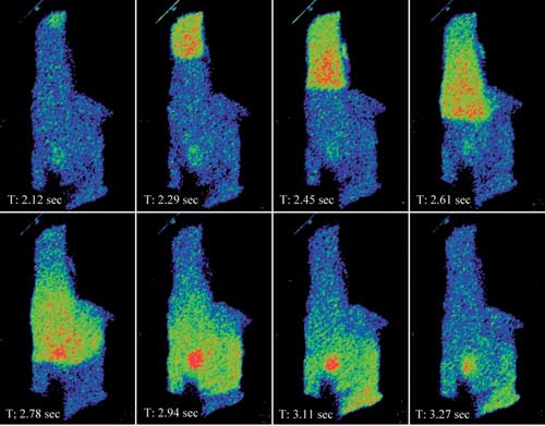
This speed allows the imaging of rapid events such as calcium
waves propagating through muscle cells or other cell signaling processes previously
impossible to accurately document with a standard point scanning confocal (Figure
1). Resonant confocals also provide short dwell times that greatly minimize the
generation of free radicals leading to phototoxicity. This allows them to be used
with very photosensitive samples and for longer experiments than traditional point
scanning confocals.

Figure 1a. Shown is an intensity pseudocolor display of a calcium wave propagating through
a rat myocyte loaded with Fluo-4. The data set was captured with Nikon Instruments’
A1R resonant scanning confocal at 60 fps.
Besides the standard benefits of a resonant scanning confocal,
Nikon, with its A1R confocal, has provided for the simultaneous use of the resonant
scanning galvanometer pair with a traditional galvanometer scanning pair. This
enables simultaneous imaging and photostimulation and prevents data loss. Previously,
a traditional galvanometer scanner would scan a base line, stop to stimulate and
then start imaging again – potentially missing the reactions that occurred
during or directly following the photostimulation. With a combined resonant and
traditional scanner, there is no loss of vital information because high temporal
resolution and high spatial resolution are both achieved.

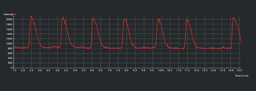
Figure 1b. Intensity-over-time graph shows multiple propagating calcium waves; seven waves
in 13 s. Courtesy of Dr. Todd Herron, University of Michigan – Center for
Arrhythmia Research.
Superresolution
The newest frontier of microscope system development is in the
area of superresolution microscope systems. Microscope systems are limited by the
laws of diffraction. Ernst Abbe characterized the resolution limit of microscope
systems in the late 1800s, and modern microscope manufacturers have designed optics
that nearly achieve that limit (~200 nm). Recently, the development of hardware,
software and sample preparation methods has allowed the creation of images with
resolution beyond the Abbe limit, down to tens of nanometers.
In structured illumination microscopy (SIM), users project a pattern
of known dimensions onto an unknown sample in various orientations. The patterned
light creates moiré fringes when it interacts with high spatial frequency information
in the sample. The moiré fringes are resolvable by the microscope system.
Because we know the pattern of illumination and can resolve the moiré fringes,
we can mathematically solve the unknown high spatial frequency (small structure)
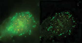
sample information. This provides for a doubling of the system’s resolution
(Figure 2).

Figure 2. On the left is a conventional epifluorescence image of human vascular endothelial
cells – Cy3: CBF1 protein, and FITC: ubiquitin-protein ligase; on the right,
a structured illumination microscopy (SIM) image. Both were captured with Nikon
Instruments’ N-SIM system. Courtesy of Dr. Shigeki Higashiyama and Dr. Hidetaka
Ohnuki, Department of Biochemistry and Molecular Genetics, Graduate School of Medicine,
Ehime University.
It is now possible to truly see once-unresolvable interactions.
Some commercial systems can be operated at speeds that allow for the application
of this technique to live-cell imaging – 600 ms per frame for Nikon’s
N-SIM.
Photolocalization superresolution techniques such as STORM (stochastic
optical reconstruction microscopy) and PALM (photoactivated localization microscopy)
work by using fluorescent probes, which can be switched to an emitting state in
small numbers in a random pattern. The emitted light from single molecules is then
localized using a Gaussian fit process. After the first set of fluorescent molecules
moves to a dark state, another population is activated, imaged and localized.
This requires many iterations on the order of 1000 to 100,000
frames to build a single superresolution image, but it also provides the highest
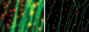
resolutions achieved in a light microscope. These methods have produced X-Y resolution
on the order of 20 to 30 nm – at near-molecular levels – opening up
a world previously limited to electron microscopy (Figure 3).

Figure 3. (Red – Clathrin Green – microtubule) left
is a conventional fluorescence image; right is a STORM image. Courtesy
of Xiaowei Zhuang, Harvard University. (Originally published in Science, M. Bates
et al (2007). Multicolor super-resolution imaging with photo-switchable fluorescent
probes, Vol. 317, pp. 1749-1753.)
Advances by optical designers and microscope engineers also have
opened up new lines of biological inquiry. Although these new lines of research
will answer previously unanswerable questions, they also will generate new questions,
again pushing the boundaries of light microscopy to go faster, deeper, longer and
sharper.
Meet the author
Joel S. Silfies is senior biosystems applications manager at Nikon
Instruments Inc.; e-mail: [email protected].