Polygonal laser scanning is the technology of choice in a variety of applications. It can be used to write information as in laser marking and printing, direct-to-plate imaging, film recording and laser projection; or as a reader for bar code scanning, densitometry, web inspection and agricultural inspection.
Glenn E. Stutz, Lincoln Laser Co.
Reading and writing systems for polygonal scanners differ in the use of the scanner. However, many performance characteristics are similar for both. In writing applications, a light source, usually a laser, is scanned by the polygon mirror to create an image line. Reading applications may use the polygon only for receiving, as in passive scene acquisition; only for transmitting laser light, such as an inspection application with a separate receive path; or for transmitting and receiving, such as in a laser radar application. This article will focus on writing applications.
Preobjective vs. postobjective
The first parameter to specify in setting up a scanning system is the number of resolvable points along a scan line. In the case of a line scanner, fewer than 10,000 points is relatively easy to accomplish. The range of 10,000 to 25,000 points requires additional complexity. If the system requires more than 25,000 points, be prepared for quite an exotic system.
The number of resolvable points together with the spot size and allowable spot size variation often determines whether the system will be of a preobjective or postobjective type (Figure 1).
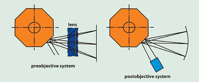
Figure 1. Scanning-system configurations.
Postobjective scanning is the lower-cost alternative, and should be evaluated first to determine whether its drawbacks are acceptable. Postobjective scanning is used when the target plane can be curved or when the depth of field is large and the scan angle is relatively small. In postobjective scanning, as shown in Figure 1, the final focusing element is located prior to the polygon. Since the beam is on axis at this point, the last focusing element can be a rather simple lens.
In preobjective scanning, a high-quality f-Theta scan lens or mirror system is used to produce a flat field and linear scan velocity on the target. This lens usually ranges from two to five elements and can be expensive. This technique is used in the majority of applications since the problems associated with postobjective scanning limit its use.
System design trade-offs
The design of a polygonal scanner can include either an underfilled or overfilled facet. An overfilled facet design typically illuminates two adjacent facets with a single beam. This design approach yields high duty cycles, but at the expense of power, variations in spot size and beam intensity uniformity. Duty cycle is defined as the ratio of the active scan time to the total scan time, where the total scan time is from start of scan to start of the next scan.
An underfilled design uses a beam significantly smaller than the facet length. This approach yields higher power and beam intensity uniformity at the expense of efficiency, and the duty cycle is in the range of 40 to 80 percent. The larger the facet length for a given beam size, the greater the percent of time spent in active scanning. The dead time with this scanner design is the time that it takes the beam to cross over the edge of the facet. The need to achieve greater duty cycles results in larger polygons.
One trade-off in system design is the number of facets vs. polygon speed. Many combinations of facet count and polygon speed can generate a given line rate. While polygons can be manufactured with many different facet counts, fewer facets result in lower cost. In addition, having more facets generally drives up polygon size, which can have a serious impact on the bearing selection and cost.
The choice of bearing systems in polygonal scanning applications can have a significant impact on system cost. Ball bearing scanners are relatively low cost and are the appropriate solution for many applications. However, they are susceptible to damage, generate many vibration frequencies and can create motor speed instability. Aerodynamic air bearing scanners use self-generating air bearings that are rugged and perform well at a moderate cost. Aerostatic scanners need external support for pressurization and are costly but offer the ultimate in scanning performance.
Ball bearing scanners typically are used in applications ranging from about 300 to 18,000 rpm. At higher speeds, the ball bearing scanners suffer from shorter lifetimes due to bearing wear. Aerodynamic air bearings can be used in the speed range of 4000 to over 60,000 rpm. The limitation on the use of the aerodynamic bearing tends to result from the load carrying capacity. Scanner manufacturers can provide more detail on the specific limitations for their standard bearings. Aerostatic bearings are used in applications ranging from a few rpm up past 60,000 rpm. These bearings are usually selected when the other bearing choices do not fit the application.
Critical polygonal scanner specifications
When specifying a polygonal scanner, the optical characteristics of the scan mirror need to be addressed. Surface figure errors on the order of λ/4 to λ/10 can be achieved without excessive cost impacts. Surface roughness values down to 75 Å rms are typical for a diamond turned optical surface, with the best diamond turned aluminum mirrors down to 45 Å rms. If a lower scatter surface is required, such as in some film printing or ultraviolet applications, then a conventionally polished optical surface will be required. The polished optical surface can have surface roughness levels down to 10 Å rms but with a serious cost penalty. This option should be used as a last resort.
The polygonal mirror needs a protective or enhancement coating which includes a low-cost aluminum with a silicon monoxide overcoat, protected gold or higher cost multilayer dielectric coating. Coatings can be tailored to fit the application whether it is in the deep-UV, visible or the mid-infrared.
One of the largest cost drivers in the design of the polygonal scanner is the dynamic track specification. Dynamic track is the angular variation in the output scans perpendicular to the scan direction from all of the facets. These errors are caused by the assembly tolerances between the mirror and the mounting hub, as well as manufacturing tolerances in the polygon mirror itself. A loose specification that is easy to achieve is 60 arc seconds, a tight specification is on the order of 10 arc seconds and a state-of-the-art specification is 1 arc second.
The following section deals with determining the proper polygon size for the application.
Polygon sizing
Once the number of resolvable points N has been specified, an active scan angle or angular resolution must be selected. In the case of a postobjective system, an angular resolution or scan angle can be specified. The relationship between these parameters is given by:

If the system is preobjective and a scan lens has been selected as a system constraint, then the scan lens defines the active scan angle. If a scan lens has not been selected, a scan angle must be assumed. Typical scan angles range from 20° to 60°. As the scan angle is increased, the number of facets and the size of the polygon decrease; however, the polygon velocity increases. A value of 45° is a good starting point and can be altered later if the result is not optimum.
From this information, the beam size on the polygon facet can be determined by:

where λ is the wavelength (μm) and D (mm) is the 1/e2 beam diameter on the facet.
The above equation assumes that the beam incident on the polygon has been apertured at the 1.5 (1/e2) diameter. Therefore, the footprint on the facet is 1.5 × D. At this point a feed angle α must be chosen. This is defined as the angle between the center line of the scanned beam and the input beam. This angle should be as small as possible to reduce polygon size. Projected footprint on the facet is defined as:

The duty cycle now needs to be selected. This is defined as the ratio of the active scan time over the total scan time. Duty cycles ranging from 50 to greater than 90 percent are common, but the greater the duty cycle, the larger the polygon and, hence, the higher the cost.
Polygon facet length L (mm) can be given approximately by:

where the value of 1 in the numerator allows for the facet roll-off at the edge. The number of facets n required on a polygon is found by:

If this turns out to be a fraction, round it off to the nearest whole number and recalculate the duty cycle and the facet length.
Polygon inscribed diameter can be determined as follows:

Polygonal scanning artifacts
Polygonal scanners create repeatable scan lines only as good as the specifications they are manufactured to. System design requires knowledge of the types of artifacts that can be produced and the techniques used to reduce or eliminate them. Several of these artifacts are discussed in the following sections.
Jitter
Jitter is the nonrepeatable variation in the pixel placement along the scan direction. Various systems can tolerate different levels of jitter before the artifact becomes visible. Visual systems typically can be specified with up to 1/2 pixel of jitter before it becomes objectionable. Output scanners that place a premium on pixel placement will typically require 0.1 pixel accuracy.
Jitter can have both random and periodic components. Random jitter is visually less objectionable than periodic jitter. The sources of jitter include facet flatness variations, facet radius variations, start of scan triggering errors and bearing load variations.
Variations in flatness from facet to facet will result in a periodic jitter with a frequency of once per revolution or higher. There will be no contribution to jitter if all facets are flat or have the same curvature. The curvature causes small deviations in the angle of reflection from the facet. A facet flatness specification on the order of λ/8 is adequate for most applications.
If the polygon is used at high speed and is attached to the mounting hub with screws, then a jitter problem will become apparent. The polygon will be constrained at these locations, causing a change in flatness at the facets that varies from facet to facet. One way to reduce this effect is to use the same number of mounting screws as there are facets and locate the screws in line with the facet tips. Another method to compensate for this error is to use a symmetric clamp mount for high-speed applications. The facets will still distort but they will distort the same, which results in no jitter being introduced to the image.
Facet radius variation can be another error source and is defined as the deviation from facet to facet of the distance from the center of the facet to the center of the axis of rotation. Facet radius variations in systems using postobjective scanning will typically show up as a sinusoidal pattern with a once-per-revolution frequency. The facet radius variation should be specified to be less than 0.001 in. to be acceptable for most scanning applications.
Random jitter errors can be produced by the ball bearings used in most low-speed scanning systems. The variation in torque required will result in small localized speed variations. The magnitude of these errors is usually small enough not to be of concern. If there is a problem, an air bearing can offer superior jitter performance at additional cost.
Start-of-scan triggering errors will result in the displacement of an entire scan line. This image displacement will be a constant from start of scan to end of scan. The triggering error can be caused by a noise on the threshold line or too slow a rise time relative to pixel size. Most systems trigger with a knife edge across a detector that is located in an alternate image plane. Systems based on silicon photodiodes or bi-cells work well in most applications.
In applications requiring accurate knowledge of the polygon location during rotation, an encoder is often attached to the rotor. The encoder can provide output pulses that range from a few hundred to many thousands per revolution. The encoder information is then used to time data collection or the writing of information during a scan. The mounting of the encoder to the rotor is a critical operation. Errors in the concentricity between the components can be significant if not addressed. Encoder mounting errors can lead to a sine wave error in the reported position. In addition, the polygon output may need to be mapped to the encoder position since it was previously mentioned that flatness errors and errors in the angles between facets will cause beam pointing to be different than expected from a linear data stream from an encoder.
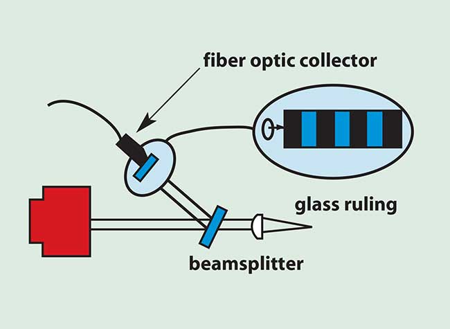
Figure 2. Optical pixel clock.
Tighter pixel-placement accuracy can be achieved by the use of an optical pixel clock as shown in Figure 2. A small fraction of the beam is split off to a glass scale with alternating clear and opaque areas. The beam passes along this scale and the light that passes through is collected. This collected energy now provides a pulse at every pixel location along the scan line. This pixel clock is referenced to actual position in the scan plane so that both random and repeatable errors are removed. This method provides ±0.1 pixel accuracy, which is good enough for virtually any system. Several other methods of pixel-placement correction also can be used.
Banding
Polygons are high-precision balanced rotating elements, but there are residual track errors on the order of a few arc seconds that must be removed in high-end systems. These errors perpendicular to the scan line are known as cross-scan errors. In a writing application, large cross-scan errors will appear as banding down the image, which is a periodic compression and expansion of the line-to-line spacing.
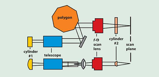
Figure 3. Cross-scan error correction technique.
Correction for cross-scan errors can take several forms. The most common is a passive technique. Typically, a pair of cylinder lenses is used as shown in Figure 3, with the first cylindrical lens producing a line focus on the polygon facet and a second cylindrical lens, toroidal lens or cylindrical mirror, reimaging this line focus to the scan plane. This is not an exact relationship because a polygon will cause pupil shifting (Figure 4), but it corrects to better than ±0.1 pixel in most applications.
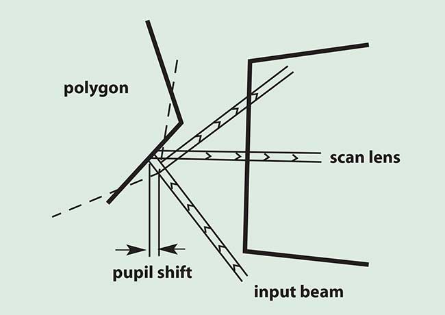
Figure 4. Pupil shifting.
A second technique for cross-scan correction is an active feedback system. This technique works when the major source of cross-scan error is the facet tilt; i.e., when the bearing is accurate to less than 1 arc second and requires no correction. The bearing-induced wobble is random and cannot be corrected by an active technique.
Active cross-scan correction systems use a detector near the start or end of line to sample the beam location in the cross-scan axis. A bi-cell is the device most often used for this purpose. The difference in output between the two halves of the bi-cell provides beam location information. This is fed to a lookup table that has a position for every facet. The output of the lookup table is used to steer the beam in the system to compensate for the error. The steering is normally done during the blanking time between scans, allowing enough time for any settling to occur. This type of correction is not very common since there is additional complexity and more active components. It is used when it is impractical to correct for the cross-scan error using passive techniques.
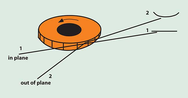
Figure 5. Scan-line bow.
Bow
Alignment of the polygon to the incoming beam is also critical. A bowed scan line results if the plane of rotation of the polygon mirror does not include the input beam. Figure 5 illustrates this effect.
System design
The design of a polygonal scanning system requires knowledge of the polygonal scanner designs available and the specifications that drive the costs. Without this information it is possible to get locked into a system concept that results in higher costs than could be achieved. As pointed out in this article, there are many combinations of scanners and optics that can result in meeting the end requirements, but the engineering challenge is to find the solution with the best cost/performance trade-offs.