Optical System Design: Keeping the Coatings in Mind
The design of optical systems should balance the coating constraints with the optical and mechanical requirements. Understanding the key properties and limitations of optical coatings enables the system designer to improve the performance of the optical system.
JDSU
An optical coating engineer is frequently confronted with a difficult specification for a coating. Often the difficulty in the specification results from the particular form of the optical system. If the optical system designer were to make a simple change to the system, the coating would be a lot less expensive. In some cases however, the coating specification cannot be changed because the system design has been frozen. The purpose of this article is to alert optical system designers to a few simple rules of optical coating, which they can consider early in their design process.
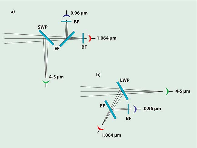
Consider the optical system shown in Figure 1a. A focused beam of light is split into several beams for detection at various wavelengths. The beam first encounters a short-wave pass (SWP) filter, which passes the near-infrared region of the spectrum while reflecting the 4- to 5-μm range into a detector. An edge filter (EF) is used to separate two laser wavelengths — 0.96 μm and 1.064 μm. In front of each of the laser-line detectors is a blocking filter (BF) to eliminate light from the other laser line. The SWP and EF are oriented at a 45° angle of incidence.

Figure 1. Two optical systems that separate laser lines near 1 μm from a 4- to 5-μm infrared band. The system depicted in (a) uses a short-wave pass filter to reflect the 4- to 5-μm band and transmit the laser lines. An edge filter is used to separate the laser lines. These two filters are used at a 45° angle of incidence. A blocking filter is used in front of each laser-line detector. In the system depicted in (b), a long-wave pass filter is used to reflect the laser lines.
Rule number 1
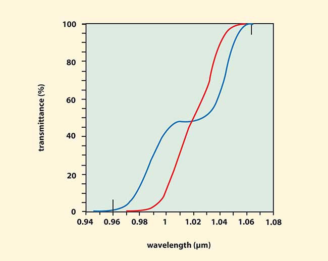
Optical coatings are always simpler and perform better at lower angles of incidence. Consider the redesigned optical system of Figure 1b. In this system the filters are at a working angle of 30° rather than 45°. Consider specifically the EF separating the 0.96-μm line from the 1.064-μm line. Figure 2 is a comparison of the transmittance of the EF designed at 45° (blue curve) necessary for the system in Figure 1a with the transmittance of the EF designed for use at 30° (red curve) for the system in Figure 1b. Vertical black lines in Figure 2 indicate the laser wavelengths. Each design uses 32 alternating layers of SiO2 and TiO2 on a fused silica substrate. The curves have been calculated for an f/8 cone of unpolarized light with the central angle as specified for each system.

Figure 2. The transmittance vs. wavelength for edge filters designed at 45° (blue curve) and 30° (red curve). The transmittance is calculated for an f/8 cone of light. Small vertical lines indicate the positions of the laser wavelengths at 0.96 and 1.064 μm.
When used at an angle, an edge filter has a jog in the middle caused by the difference between the transmittance of the filter for S- and P-polarized light. For the filter designed for 45°, this jog makes the transition region so wide that it is just barely possible to achieve high transmittance at 1.064 μm while blocking 0.96 μm. There is almost no room for wavelength error (less than ±0.5 percent tolerance), and the transmittance at 0.96 μm is 0.9 percent for the design shown. On the other hand, the design at 30° has about ±1.5 percent of wavelength tolerance and the transmittance at 0.96 μm is 0.07 percent. Clearly the design at 30° has better performance and more manufacturing tolerance. Depending on the rejection level required, it might be possible to eliminate the blocking filter in front of the 1.064-μm detector in the 30° system since the transmittance of the 0.96-μm band of the EF is so low.
It should be mentioned that there are more advanced edge filter designs, which could be made to give better performance at 45°, but the point is made that it is easier to get good performance at smaller angles of incidence.
Rule number 2
A long-wave pass (LWP) filter is easier than a short-wave pass filter. In the system in Figure 1a, the 4- to 5-μm band is reflected by a SWP filter. In the system in Figure 1b, the 4- to 5-μm band is transmitted by a LWP filter requiring a substrate that is transparent in the 4- to 5-μm range. For the design example, CaF2 was chosen, but ZnS or ZnSe would work just as well. Note that these substrate materials are more expensive than the glass or fused silica that could be used with the SWP filter, but the extra expense is offset by the improved performance and manufacturing tolerance of the LWP filter as demonstrated below.
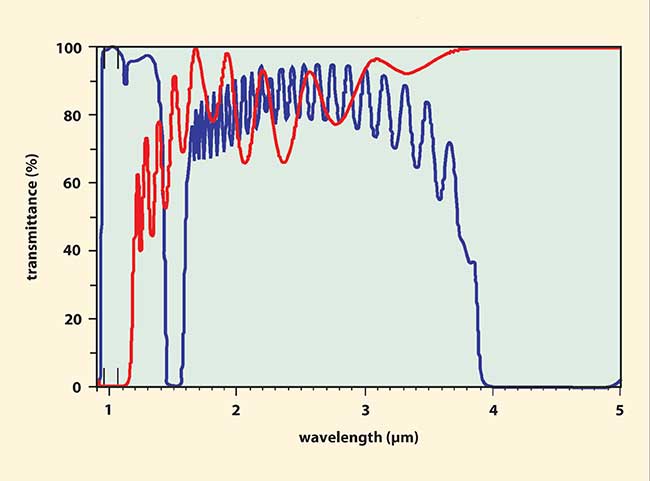
Figure 3 compares the transmittance of a SWP filter at 45° with that of a LWP filter at 30°. The curves have been calculated for an f/8 cone of light. A major drawback of the SWP filter is that the transmission region has a limited wavelength range. The SWP filter (blue curve) has its primary reflection band covering the range of 4 to 5 μm. However, there is a third-order reflection band at about 1.5 μm and a fifth-order band at about 0.9 μm. There is also a transmission dip at the position of the fourth order at about 1.13 μm. The two laser lines just fit between the fourth- and fifth-order features with essentially no wavelength tolerance. On the other hand, the LWP filter (red curve) has no reflection bands beyond its edge at about 1.2 μm. The primary reflection band reflects both laser lines. There is plenty of design freedom to produce a good antireflection coating covering the 4- to 5-μm range.

Figure 3. The transmittance vs. wavelength for a short-wave pass filter designed for 45° (blue curve) and a long-wave pass filter designed for 30° (red curve). The laser lines at 0.96 μm and 1.064 μm are indicated by small vertical lines. The SWP filter has reflection bands at 1.5 μm and 0.9 μm, which interfere with achieving high transmittance over a broad band. The LWP filter does not have these features and high transmittance over the 4- to 5-μm range is easy to achieve.
More advanced designs using three or more coating materials can be employed to remove unwanted reflection bands of the SWP filter, but the point has been made: LWP filters are generally simpler.
The transmission ripples constitute another advantage of the LWP filter. Notice the ripples beginning at about 1.3 μm, immediately above the reflection band. The SWP filter also has ripples at wavelengths just below its band edge at 4 μm. (For the current specification, these ripples do not matter.) In general, it is easier to get rid of the ripples close to the band edge for the LWP filter than for the SWP filter. This factor is important if a sharp cut-on or cut-off is needed, as in the EF separating the laser lines, which is a LWP filter. Notice in Figure 2 that there is no evidence of the ripples in the high-transmission region close to the band edge.
Rule number 3
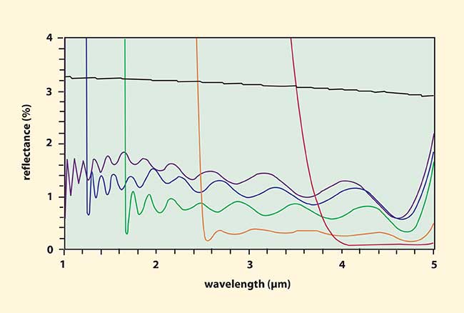
An antireflection coating with a bandwidth ratio of more than 2:1 is difficult. The LWP filter shown in Figure 1b needs an antireflection (AR) coating on the second surface to cover the range of 4 to 5 μm. This presents an opportunity to compare designs for several AR coatings in Figure 4. All of the reflectance curves are for unpolarized light incident at 30°. The red curve is for an AR coating covering the range of 4 to 5 μm, useful for the back of the LWP filter in Figure 1b. The average in-band reflectance is 0.08 percent and the design uses five layers. The other curves in Figure 4 illustrate AR coatings covering wider wavelength ranges. The orange curve covers the range from 2.5 to 5 μm. The ratio of these wavelengths is 2:1. The average reflectance is 0.28 percent and the design uses 12 layers. The other curves are green for a 3:1 range (1.67 to 5 μm), blue for a 4:1 range (1.25 to 5 μm) and violet for a 5:1 range (1 to 5 μm). The black curve represents the reflectance of a CaF2 surface at 30°.
Table 1 summarizes the results for the various AR coatings. Columns 1 and 2 give the wavelength range and ratio defining each AR. The number of layers and average in-band reflectance at a 30° angle of incidence for unpolarized light are given in columns 3 and 4. As the range gets wider, the number of layers increases and the average reflectance goes up.
TABLE 1.
COMPARISON OF AR COATINGS WITH VARIOUS WIDTHS
|
Wavelength
Range (µm) |
|
Wavelength-
Range Ratio |
|
Number of
Layers |
|
R average (%)
in band: 30° |
|
R average (%)
in band: 0° |
|
R average (%)
in band: 45° |
| |
|
|
|
|
|
|
|
|
|
|
|
| |
4 - 5 |
|
1.25:1 |
|
5 |
|
0.08 |
|
0.02 |
|
0.50 |
| |
2.5 - 5 |
|
2:1 |
|
12 |
|
0.28 |
|
0.20 |
|
0.75 |
| |
1.67 - 5 |
|
3:1 |
|
17 |
|
0.73 |
|
0.63 |
|
1.31 |
| |
1.25 - 5 |
|
4:1 |
|
21 |
|
1.09 |
|
0.96 |
|
1.73 |
| |
1 - 5 |
|
5:1 |
|
26 |
|
1.30 |
|
1.16 |
|
1.97 |
Columns 5 and 6 are the average in-band reflectances of AR coatings similar to the ones designed for 30°, but reoptimized for use at 0° and 45°. As expected, the performance at 0° is the best. The penalty for working at 30° ranges from 0.06 percent to 0.14 percent. The additional penalty for working at 45° ranges from 0.42 to 0.67 percent. This is further confirmation of rule number 1: Keep the angles as small as possible.
Rule number 4
You may not be able to make what you have designed. This is a general rule. The AR coatings in Table 1 are a good illustration. Often, controlling the deposition process for an AR coating with more than about 12 layers is difficult, so the theoretical performance illustrated for the AR coatings with bandwidth ratios greater than 2:1 would be difficult to achieve in practice, even though the calculated performance might meet the system requirements.
Some design techniques produce designs with many thin layers. Layers with thicknesses below 10 nm are typically difficult to make accurately. Coatings requiring three or more coating materials or nonstandard coating materials are more difficult. Some materials have a maximum thickness that can be used in a given coating and if the maximum is exceeded, the coating suffers stress fractures.
Another aspect of being able to make a particular filter is being able to measure it. The producer of the coating must be able to measure it in order to make it. The user of the film must be able to measure the coating to verify its performance against specification. A difficulty arises if the user's specification is a functional one — the system works — that cannot be translated easily into specific performance specifications.
Rule number 5
Don't over-specify the coating requirements. This is a general rule, which applies to all aspects of a system — optical, mechanical, etc. Figure 4 and Table 1 illustrate the cost of specifying a wider wavelength band for an AR coating. If the wide band isn't necessary, don't ask for it.
Part of specifying a system includes an awareness of the materials being used at various points in the system and what their ranges of transparency are. Silicon and germanium are common materials for long wavelength applications due to their very low absorption over a broad range of infrared wavelengths. However, they are opaque to visible light. If a visible alignment laser used in one part of an optical system encounters an optic coated with silicon or germanium, the light cannot get through. From the point of view of the specification, there is no reason to include a specification at the alignment laser wavelength for optics beyond the opaque one. On the other hand, if alignment of the whole system is important, then alternate coating materials must be used for the optic in question.
Other considerations
Figure 4 illustrates another important feature of a specification, common to most systems that are designed by an optimization procedure: once you get outside of the specified reflectance region, the performance degrades very quickly. For the cases illustrated in Figure 4, the reflectance climbs to a value in excess of the uncoated substrate within 0.5 μm for the 4- to 5-μm design and within less than 0.005 μm for the 5:1 design. All of the designs reach a reflectance of 80 percent or more outside of their specified ranges. The implication is that it may not be possible to specify the performance over a specific range and later decide to use the system over a slightly wider range.

Figure 4. Reflectance vs. wavelength for five AR coatings and an uncoated CaF2 surface (black curve) calculated for a 30° angle of incidence. The AR coatings differ in their bandwidths. The wider the bandwidth, the higher the average reflectance.
An important aspect of specifying the reflectance level for an AR coating is to take into consideration the effects of the reflected light. If the main effect of the reflection is to reduce the throughput of the system, then the difference between 0.3 percent reflectance and 0.1 percent reflectance is the difference between 99.7 and 99.9 percent transmittance for a surface. Even with several surfaces, this is a small difference in throughput but could amount to a significant difference in coating difficulty and cost. On the other hand, sometimes it is the reflected light itself that is the problem. Consider a computer monitor — for example, a cathode-ray tube display. In this case, the reflected room light is competing with the image from the screen and needs to be kept to a minimum. The difference between 0.3 and 0.1 percent average reflectance is significant and is worth the extra cost. Similar considerations apply to camera lenses where internal reflections from specific surfaces can lead to ghost images of bright objects in or just outside of the field of view.
In summary, the coating requirements should be considered early on in the design of an optical system. The requirements for each optic should be reviewed in terms of the total system performance. Some important rules about coatings have been presented. Of course, some complex optical systems may require that these rules be violated and that the coatings be more challenging and expensive. If possible, an optical coating engineer should be included on the design team along with the optical system, mechanical and electrical engineers. This practice will help to reduce the complexity and cost of the system.
/Buyers_Guide/Lumentum_Operations_LLC/c7335