Dr. Joost Van Kuijk, Adimec
An explanation of performance and tips on reducing system costs using cameras with image processing capabilities.
Perfect image sensors or lenses do not exist; all have artifacts, introduce noise and distort the “real” image. Even high-quality CCD and CMOS image sensors produce artifacts. In many machine vision OEM instruments, the industrial camera is a critical component, and these artifacts should be eliminated or corrected. Image correction functions can be implemented in the camera, performed by frame grabbers or via software in PC systems such as advanced color-processing algorithms, local and global flat-field correction, defect pixel correction, noise reduction algorithms, image uniformity and stability issues,
and many more.
Improved accuracy is the main advantage of having advanced in-camera functionality or processing, as opposed to doing this off the camera and elsewhere in the system. In-camera processing also offers the flexibility to create cost reductions somewhere else in the system.
In-camera memory and image processing can improve system performance by adding factory calibrations to the camera, allowing in-field optical system calibrations and advanced correction algorithms.
Every image sensor technology has its peculiarities. With CMOS sensors, for example, interframe stability and nonuniformities between pixels can be a concern. For CCD image sensors, there are nonuniformities from each output (channel). Even more dramatic are channels, columns and pixels that may show different nonlinearity characteristics.
Sensor selection and calibration can compensate for many artifacts during the camera production process. When the root cause of image sensor artifacts is understood, appropriate calibrations can be created via modeling and then implemented in the camera. After camera calibration, the artifacts in the image data are within the boundaries of the image processing capabilities of the camera, resulting in stable and reliable performance during its entire operation, and long-term stability guarantees can be made. In-production calibrations are closer to the source, so they are more effective than having calibration done elsewhere in the image chain.
Depending upon the image sensor batch quality, artifacts are less or more present and sensitive to external conditions such as temperature. This can be optimally controlled and managed during the camera’s production and operation.
In-camera processing achieves higher image accuracy, even at high speeds, because the algorithms in the camera usually use a very high bit depth for internal calculations. Processing of the images elsewhere in the system cannot meet the level of accuracy because the calculation bit depth on the frame grabber is limited by the bit depth over the interface link.
Case 1: Optimal image uniformity
This case is from a customer who develops sophisticated medical diagnostic systems. Previous generations of the system used their own in-house-developed cameras and image processing software. This included advanced flat-field correction (FFC), processed in the frame grabber.
For the latest upgrade of their system, three cameras from different suppliers based on the CMOSIS CMV4000 sensor were evaluated, including the Quartz Q-4A180 from Adimec. They did not expect any difference in image uniformity among the cameras. Although each camera is using identical image sensors, the other two cameras combined with this customer’s own off-camera image processing performed worse than Adimec’s camera with just the in-camera image processing.

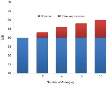
Frame speed of the Adimec Q-4A180 for various noise improvement scenarios. In-camera processing achieves high image accuracy, even at high speeds. Images courtesy of Adimec.
The reality is that no matter how good the FFC is on the frame grabber, it will not be as accurate as what can be done on the camera when the sensor characteristics are fully understood.
Case 2: Accurate image averaging
Averaging improves the shot-noise performance of the image sensor. Our in-camera image processing can add a 10-dB improvement. Averaging within the camera is performed at a bit depth and frame speed not possible in Camera Link-based frame-grabber environments. High data rates with Camera Link are restricted to 8 bits per pixel. Averaging in the PC/frame grabber at high acquisition speeds (>80 fps with 4 megapixels) is therefore based on 8-bit input only, whereas the Adimec Quartz camera uses the full 10 bits from the sensor. This makes for higher accuracy in averaging results.
Binning, averaging
Two techniques, or a combination thereof – binning and averaging – can reduce noise to increase dynamic range. Binning reduces electronic circuitry noise, and frame averaging reduces both electronic circuitry noise and shot noise.
In some cameras, both functions can achieve noise improvements of up to 12 dB in the performance of the sensor. With binning, the resolution of the camera decreases, but the maximum camera frame speed remains intact.

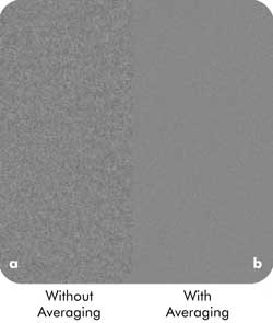
With frame averaging, the camera’s resolution stays the same, but its maximum frame speed drops. Here is an example of dynamic range expansion with binning and averaging (enhanced contrast). On the left is an image with no averaging; on the right, the same image has been averaged.
With frame averaging, the resolution of the camera remains the same but the maximum frame speed drops. A shot-noise improvement compromise between averaging and speed can be found by applying region-of-interest imaging, which increases the acquisition speed of the camera and can be used to compensate for the drop in speed by averaging.
In the past, shot-noise critical measurements could be addressed in cameras only with the use of sensors with high full well; e.g., 40 ke– and higher. Although shot-noise dominance can be controlled this way, acquisition speeds often are too low to meet today’s needs. Sensors that can address the speed needs, in general, have low full-well levels to achieve their performance. Because these sensors also have lower read noise levels, similar and even better dynamic ranges are achieved. But this dynamic range number can be misleading: Shot noise at lower full-well levels becomes a more dominant noise source for affecting accurate detections in “white.”
Shot-noise reduction with frame averaging is the perfect example of optimizing system costs through processing in the camera because it reduces the data load on the camera interface and PC-frame grabber processing.
A question that users must address: Would functionality in the camera – such as color processing to eliminate strains on resources elsewhere in the system or window of interest to eliminate processing irrelevant data – be beneficial?
Cameras that include image processing functionality are ideal for OEMs looking for upgrades to their systems in terms of accuracy, cost or both.
They also are ideal for system builders who want a simpler system as well as for managers and designers who want to focus on advancing their measurement and analysis software rather than doing image processing to compensate for an inadequate starting image.
Meet the author
Dr. Joost van Kuijk is vice president of marketing and technology at Adimec in Eindhoven, Netherlands; email: [email protected].
Three tips for reducing system costs
Tip 1. Focus on core competencies: Expensive software resources can be spared when no workarounds have to be created for inefficient camera performance. Software designers can focus on supporting the company’s core competencies rather than worrying about poor image quality.
Tip 2. Save on frame grabbers and PCs: Many systems are not performing constantly but make mechanical motions during which no images can be taken. Depending upon the OEM equipment architecture, it is sometimes beneficial to decouple the image acquisition speed of the image sensor from the interface data transfer speed, or data rate. While the images are acquired at full speed, the full time between inspections is used to transfer the data. This can be done with in-camera image processing and memory. Some image processing functions use multiple images to create one enhanced image. When this is done in the camera, the images per second can be reduced by a factor of 10 or even more – this can be the difference in using a two-tap Camera Link frame grabber or an expensive 10-tap version.
Tip 3. Simplify your system design: With the image processing in the camera, manufacturers can add automatic adjustments through direct loops that autocorrect for temperature changes during operation, lighting conditions, lens defects or other specific system conditions. For example, with flat-field correction, some cameras also support in-field calibration. This allows for corrections of the image acquisition setup process, such as nonuniformity of lighting source(s) and optics used in setup. Some cameras support storage of multiple calibration “image maps” and can switch between different lighting-optics setups instantly during operation. This can ease system integration and avoids the development of calibrations on dedicated field-programmable gate arrays or digital signal processing in the PC.