Marco Mendes and Jeffrey P.Sercel, J.P. Sercel Associates Inc.
In today’s society,
there is a continuous need for devices with lower energy consumption and higher
efficiency. Light-emitting diodes (LEDs) are expected to see a 61 percent rise in
worldwide demand in 2010, according to Barry Young of IMS Research, due in large
part to the mobile handset. The market for large backlit LED TVs is rapidly expanding,
and LEDs also are used in a large number of other applications, from projectors
and flashlights to car tail- and headlights and general illumination. Solid-state
white-light sources can be realized either by mixing different LEDs emitting red,
green or blue light, or by using a phosphor material to convert monochromatic light
from a blue or UV LED to broad-spectrum white light.
With the increase in LED production, manufacturers are looking
for new process developments to optimize scribe width, speed and production throughput.
New advances in laser liftoff (LLO) and laser wafer scribing for LEDs provide manufacturers
with cost-effective industrial tools that are ready to meet increased demands.
High-brightness LEDs with vertical structure
Typically, blue/green LEDs are composed of a GaN film a few microns
thick, grown epitaxially on a sapphire substrate. Some of the major costs of LED
fabrication are the sapphire substrate itself and the scribe-and-break processes.
For the traditional LED configuration, the sapphire is not removed, so both cathode
and anode are installed on the same side of the GaN epitaxial (epi) layer (Figure
1).
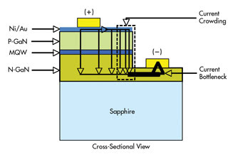
Figure 1. This diagram shows the traditional horizontal configuration for a
blue LED. MQW = multiple quantum well.
There are several drawbacks to this configuration. For high-brightness
LEDs, disadvantages include a high current density inside the material, current
crowding, reduced reliability and shorter lifetimes. Also, there is significant
light loss through the sapphire.
By using an LLO process, LED designers can create a vertical LED,
which overcomes many of the limitations of the traditional horizontal configuration.
Vertical configuration provides the possibility of pumping an LED with more current,
eliminating the undesired current crowding and bottleneck inside the device and
significantly increasing the maximum light output and efficiency of the LED (Figure
2).
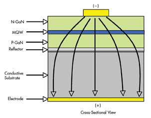
Figure 2. A model of a vertical configuration for a blue LED is shown.
The vertical LED structure requires removing the sapphire before
attaching the electrical contacts. Excimer lasers have proved to be valuable tools
for separating the sapphire and GaN thin film. LED laser liftoff dramatically reduces
the time and cost of the LED fabrication process, enabling the manufacturer to grow
GaN LED film devices on the sapphire wafer and to transfer the thin-film device
to a heat sink electrical interconnect. The process allows for creation of freestanding
GaN films and integration of GaN LEDs onto virtually any carrier substrate.
Laser liftoff principle
The basic concept behind UV LLO is to use the different absorptions
of UV laser light in the epi material and the sapphire. With a high (9.9-eV) bandgap
energy, sapphire is transparent to 248-nm KrF excimer laser radiation (5 eV), whereas
GaN (approximately 3.3-eV bandgap) strongly absorbs the 248-nm laser light. As shown
in Figure 3, the laser light travels through the sapphire and couples with the GaN,
causing ablation at the GaN-sapphire interface. This creates a localized explosive
shockwave and debonds the GaN from the sapphire at that location. The same principle
applies to AlN on sapphire when using 193-nm ArF excimer laser radiation. Aluminum
nitride with a bandgap of 6.3 eV can absorb the 6.4-eV ArF radiation, but AlN is
still transparent to sapphire with a 9.9-eV bandgap.
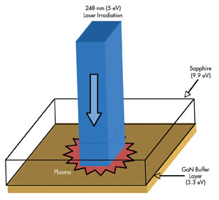
Figure 3. This is a schematic representation of laser liftoff at 248 nm.
To achieve successful liftoff, both beam homogeneity and wafer
preparation are important. At J.P. Sercel Associates (JPSA) Inc., innovative and
patented beam homogenization techniques with excimer lasers create a flattop beam
on the wafer with uniform energy density distribution across an area as large as
5 x 5 mm.
Correct wafer preparation is crucial for successful LLO. It minimizes
the residual stress from the high-temperature epi layer growth on sapphire, and
it ensures adequate bonding between the epi layer and the carrier substrate to avoid
fractures along the epi during liftoff. Figure 4 shows a typical liftoff result.
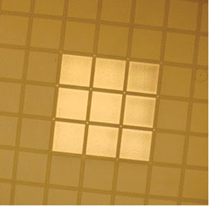
Figure 4. This diagram illustrates single-pulse laser liftoff of GaN from
sapphire at 248 nm (one pulse covers nine die).
Using LLO systems leads to high-speed, high-yield production at
ambient temperature. Well-designed systems allow exposure of multiple die simultaneously
with a single shot and permit accurate placement of each shot across the wafer using
a novel “fire on the fly” technique.
Blue LED wafer scribing
There are traditional manufacturers who continue to supply horizontal-structure
blue LEDs, and laser scribing is ideal for processing this wafer configuration.
The extreme hardness of the sapphire causes significant problems for both saw dicing
and diamond scribing, including low die yield, low throughput and high operating
costs.
The use of UV diode-pumped solid-state (DPSS) lasers has proved
to dramatically increase die yields and wafer throughput as compared to traditional
diamond scribing methods, without appreciable loss of brightness in LED wafers.
The short wavelength enhances optical absorption at both the GaN and sapphire layers,
lowering the irradiance required for ablation while simultaneously allowing for
reduced cut width.
Scribe width, speeds and production throughput are essential to
keeping manufacturing costs low and wafer yields high. JPSA has developed a patented
beam delivery system that allows for a very narrow kerf of 2.5 μm wide (Figure
5) and offers proprietary surface protection that minimizes debris. Moving the wafer
under a tightly focused laser beam produces an extremely narrow V-shape cut; starting
at the epi side and extending into the sapphire, it is typically 20 to 30 μm
deep. After laser scribing, V-shape laser cuts act as stress concentrators for the
process of breaking with standard cleaving equipment.
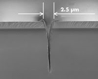
Figure 5. Shown here is the kerf width in a GaN-on-sapphire wafer.
The narrower kerf width generated by 266-nm front-side scribing
increases the number of usable die produced per wafer, potentially boosting the
entire fab operation.
An easy comparison involves a typical 2-in. blue LED wafer on
sapphire, with 250 x 250-μm devices. Using traditional diamond scribing with
typical 50-μm streets (300-μm die pitch), there will be approximately
22,500 die on the wafer. The typical breaking yield is 90 percent for traditional
diamond scribing and results in 20,250 usable die per wafer.
By using UV laser scribing, the street width can be reduced to
20 μm (a 270-μm pitch), increasing the number of die on the wafer to approximately
27,800 (a 23 percent increase). With increased breaking yields, the method produces
about 27,500 usable die – a 35 percent total increase in usable die per wafer.
Since 1996, JPSA has been using 266-nm DPSS lasers to scribe blue
LED sapphire wafers from the GaN front side at speeds of 150 mm/s, leading to a
throughput of about 15 wafers per hour (for standard 2-in.-diameter wafers with
a die size of 350 x 350 μm). With its high throughput and minimal impact on
LED performance, the process is tolerant of wafer warp and bow, delivering much
faster scribing speeds than traditional mechanical methods.
Scribing silicon carbide
In addition to sapphire, silicon carbide can be used as an epitaxial
growth substrate for thin blue LEDs. Ultraviolet DPSS lasers at 266 and 355 nm (4.6
and 3.5 eV, respectively) excel at scribing silicon carbide, which has a large bandgap
of around 2.8 eV. Because of the high photon energy, enhanced coupling is achieved,
allowing for high-speed scribing and easy breaking. Thick III-nitrides such as GaN
and AlN also can be scribed using UV DPSS lasers. While the scribing speed for 200-
to 400-μm-thick GaN or AlN is significantly reduced compared with the speed
for thin epi films on sapphire or silicon carbide, the cut quality is excellent
and allows for a clean breaking step.
For vertical high-power LEDs, LLO detaches the sapphire while
the epi film remains bonded, typically to a high-conductivity carrier substrate
such as copper, copper-tungsten, molybdenum or silicon. For wafer-based silicon,
cutting depths of 100, 150 and 200 μm can be achieved at 300, 150 and 100 mm/s,
respectively. Beam delivery techniques allow these scribing speeds/depths while
requiring only limited laser power and, consequently, minimizing thermal affectation.
Scribing of metal-based wafers is challenging because of high thermal conduction
that typically leads to a weld back effect. In addition, a full cut often is required
for separation because the material is extremely ductile. At JPSA, we have developed
advanced techniques that allow for successful scribing of these substrates up to
200 μm thick and that could prove extremely important for the high-brightness
LED industry.
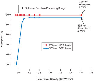
Figure 6. This graph represents UV absorption in LED sapphire.
Dual scribing capability
Back-side scribing by 355-nm DPSS lasers allows scribing from
the sapphire side of the LED. Wafer alignment can be performed from the front or
back side using multiple inspection cameras, which is important if the sapphire
has a metallic reflective layer. Also, the epi is not directly exposed to laser
radiation, which may minimize light loss. When compared to a 266-nm laser, the longer
355-nm wavelength leads to reduced absorption in the sapphire (Figure 6). As a consequence,
higher power typically is required, which leads to wider kerfs and streets. Additionally,
back-side scribing is applicable only for sapphire wafers <150 μm thick,
while front-side scribing allows for thicker wafers that may be lapped down to the
final thickness required for breaking after processing.
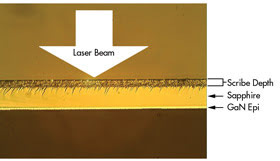
Figure 7. Shown here is a cross section of a GaN wafer scribed from the sapphire (back)
side by a 355-nm diode-pumped solid-state laser.
With continued research and development in back-side scribing,
such as new laser absorption enhancement techniques, JPSA has achieved high-throughput
back-side scribing at speeds of up to 150 mm/s with no debris or damage to the epi
layer (Figure 7).
Wafer scribing III-V semiconductors
An alternative method for separating brittle compound semiconductor
wafer materials in GaAs, InP and GaP wafers is scribing with UV DPSS lasers that
rapidly process wafers with kerfs around 3 μm with no edge chipping in any
of the III-V materials, making straight, accurate and clean cuts (Figure 8). Typically,
wafers up to 250 μm thick are scribed at 300 mm/s, allowing for easy breaking
(Figure 9). The III-IV wafers are expensive, so wafer real estate is valuable. The
tighter, narrower and cleaner cuts achieved using UV lasers provide a better die
count per wafer as well as higher yields, due to fewer damaged die than with conventional
saw scribing methods.
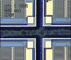
Figure 8. Clean, well-defined edges are highlighted in this scribed and expanded GaAs wafer.
Outlook
LED technology is advancing rapidly as it strives for higher efficiency
and lower manufacturing costs. This “green” technology undoubtedly has
a bright future; however, it also faces considerable challenges.
The current explosion of worldwide demand for LEDs requires the
development of new laser processes and technologies to produce even higher quality,
yield and throughput. In addition to the ongoing development of laser systems, new
machining techniques and applications, improved beam delivery and optical systems,
and an enhanced knowledge of the interactions between laser beams and materials
will be required to sustain the progress of this green revolution.
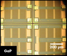
Figure 9. Pictured is GaP scribing at 300 mm/s for a 30-m cut, which is deep enough to
break wafers up to about 250 μm thick.
Equipment engineers are challenged to build flexible tools. Options,
such as the capability for automated cassette loading and unloading, edge detection
and auto-focus systems, define the state-of-the-art laser scribing solution. Companies
such as JPSA continue to explore the forefront of laser technology to meet the demands
of the LED manufacturing market.
Meet the authors
Jeffrey P. Sercel is chairman and chief technology officer of
JPSA in Manchester, N.H.; e-mail: [email protected]. Marco Mendes is director
of JPSA’s applications lab; e-mail: [email protected].