Jörg Latzel, Yokogawa Europe
New solutions for fast and accurate wavelength measurements use interferometer technology, which offers a number of benefits compared with classic spectrum analysis.
As soon as highly accurate wavelength measurements are required, calibration and long-term stability in the measuring instrument become significant factors. Any specification referring to accuracy alone only gives half the picture: The long-term stability is the essential other half. For continuous, accurate wavelength measurement, a continuous reference is required, and there are significant differences between the types of reference used in different optical measurement solutions.
Wavelength measurements can be executed using different measuring principles. Spectrometers, grating-based spectrum analyzers and echelle spectrometers all deliver good wavelength measurement results, with accuracies down to 10 pm. It is important to point out, however, that this accuracy is based on a separate calibration process carried out before or after the measurements. This means that the measurement requires highly stable environmental conditions that have to be maintained during both calibration and measurement to achieve the specified accuracy.

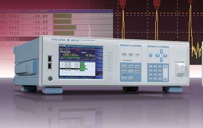
The Yokogawa AQ6150 and AQ6151 optical wavelength meters feature a high wavelength accuracy (±1 pm for the AQ6150 and ±0.3 pm for the AQ6151), and can carry out simultaneous measurements on up to 1024 channels in the telecommunications wavelength range from 1270 to 1650 nm. Images courtesy of Yokogawa Europe.
In many cases, the calibration will have been carried out by the instrument manufacturer under environmental conditions that are completely different from those encountered in the real test environment. This may lead to unexpected inaccuracies – particularly those due to temperature effects. For example, a temperature change of about 10 K can result in a wavelength measurement difference of up to 50 pm using old grating-based optical spectrum analyzers. Modern production models can still show a shift of more than 10 pm over a temperature difference of 10 K.
These deviations caused by temperature differences must be considered by users carrying out calibration using absorption cells like the SRM2517 acetylene gas cell (SRM refers to Standard Reference Material as defined by NIST). This type of calibration is used on grating-based spectrum analyzers and is performed using between one and three reference wavelengths that form the base for a total wavelength correction value. Since these calibrations are typically carried out before or after the measurement on the device under test, a stable environmental condition over the intervening period is required. Measurement accuracies of
better than 10 pm are virtually impossible to achieve using this technique.

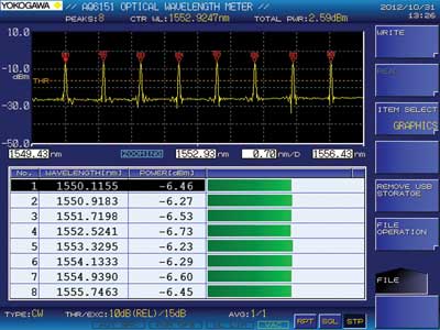
This screen shot shows a Fabry-Perot laser measurement carried out using the Yokogawa AQ6151 optical spectrum analyzer.
New wavelength meters
New developments in wavelength meters now allow multiwavelength measurements to be carried out with accuracies of 0.2 parts in 106; actual results include 0.3-pm accuracy at 1550 nm (as with the Yokogawa AQ6151) or 1 pm at 1550 nm (as with the AQ6150). Moreover, these results are unaffected by temperature changes in the range discussed above.
These high accuracies fit perfectly with many different applications. In the DWDM (dense wavelength division multiplexing) sector, wavelength meters have been used for years. Other areas requiring the highly stable and accurate wavelength measurements provided by the new generation of wavelength meters include lasers for spectroscopy, coherence tomography and lidar applications, as well as tunable lasers, and tunable laser array development and production.
In the telecommunications area – especially in metro and long-distance networks – there is a demand for either increased bandwidths or reduced channel spacing. The combination of these trends – particularly the decrease in channel spacing – in combination with higher modulation rates requires more accurate laser adjustments, since channels may overlap if not accurately adjusted. These adjustments – which include both the DFB (distributed feedback) transmitter and the transceivers – are typically carried out using wavelength-meter measurements during the tuning process.

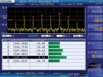
This screen shot shows 100-GHz spacing in a DWDM (dense wavelength division multiplexing) signal.
A further potential application for these wavelength meters is in WDM (wavelength division multiplexing) systems, which in the midterm are expected to be introduced into the passive optical access network (PON) systems used in FTTH and related systems to satisfy the required data rates. These applications will also require more accurate laser wavelength measurements.
Monochromator vs. interferometer
In situations where the wavelength accuracy and the measurement speed are both a high priority, either extremely stable environmental conditions are required or a continuous reference measurement must be taken during the tests. A classic grid-based monochromator cannot handle a continuous reference simultaneously with the measurement, so Michelson-based interferometry offers a number of benefits in this scenario.
A Michelson interferometer-based wavelength meter consists of two detectors: one to evaluate the reference light and the other to capture the test signal. For the test signal, the AQ6150/51 wavelength meters are equipped with InGaAs-based photodiodes.
In addition to the detector, the block diagram shows the beamsplitter and two optical paths as well as a HeNe-based reference laser. A barometer can also be incorporated to capture the air pressure and to correct the optical path lengths that can change with varying air pressure.
Both light beams – that of the test signal as well as that of the reference signal – pass through the beamsplitter. From there, both signals are diverted into two directions and pass along both optical paths: that of the fixed mirror and that of the movable mirror. The light beams reflected by the mirror will be diverted to the beamsplitter again and reflected from there to the photodetectors. At the detectors, an interference signal will be created, which will depend on the phase difference between the optical paths (fixed mirror and movable mirror).
If the phase difference is zero, there is maximum light at the photodetector (if the source has a single wavelength). If the signal is out of phase, there is no light at the detector. For the reference photodetector, there is only the HeNe signal, and while continuously changing the path differences, this signal is sinusoidal, alternately high and low. The signal at the reference photodetector is therefore used to evaluate the changing path lengths. One cycle represents a path change of double the reference light wavelength. This information represents the time information later used to execute the Fourier transformation that is caused by the test signal at the signal photodetector.
The great advantage of this principle is that the stable reference laser is always actively supporting the measurement. Any temperature change that might have an influence on the path lengths is the same for the reference and for the test signal; any possible change is therefore automatically compensated. Potential air pressure changes are compensated by mathematical correction using barometer results.
The difference between traditional interferometer designs and the new instruments is that there is no fixed mirror. A mechanical change of one path directly changes the length of the other path in the opposite direction. If one path gets longer, the other gets shorter, and vice versa. Using this principle, a much higher sweep speed can be achieved, leading to a full wavelength sweep within 0.3 seconds. This is a uniquely short measurement time achieved by these new test and measuring instruments.
Meet the author
Jörg Latzel is T&M sales manager at Yokogawa Germany based in Herrsching; email: [email protected].