Researchers are building a mechanical firefighter that will work inside the flames.
Faruk Keceki, IZMIR Institute of Technology
Some machines can be used to find fires or to extinguish them from afar, but saving the lives of people trapped within a burning building requires a machine that can take a little singeing. A remotely controlled robot being designed and built at the Izmir Institute of Technology in Izmir, Turkey, will ultimately explore a fire zone and look for survivors. To survive inside the fire, the robot uses both passive and active cooling systems that, for a limited time, keep the inner temperature at a safe level for the electronic components inside the device.

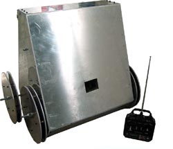
Figure 1. Shown is a remote-controlled firefighting robot with a CCD camera behind a fireproof glass window.
Rough conditions
Two problems must be solved when designing a fireproof firefighting robot. The first is maintaining an operating temperature appropriate for the electronics. In a normal house fire, the temperature can rise up to 850 °C (>1500 °F), whereas the electronics should be kept under 55 °C (130 °F). The second design problem centers around navigation inside a flame-filled environment. Because infrared light emits from burning objects, IR sensors cannot be used to measure distance. Moreover, ambient smoke makes it impossible to use CCD cameras.
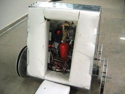
To prove the concept that a robot can work inside a fire, institute researchers built a prototype robot (Figures 1 and 2). Figure 1 shows the front view, where the camera opening is covered by a fireproof glass; Figure 2 demonstrates the back view, where the passive insulation and the fire extinguisher tube can be seen.

Figure 2. A passively insulated robot with a built-in fire extinguisher can sweep rooms in burning buildings, look for survivors and help emergency personnel.
The body of the robot is made of aluminum and comprises two shells attached to each other with rods. To slow down the heat flow between the outer and inner shells, the gap is filled with rock wool and ceramic paper as insulation material. The robot is controlled with a remote unit by an operator, who can observe the fire via a CCD camera made by Monacor International GmbH of Bremen, Germany, inside the robot. The camera has a 512 × 582-pixel array and 380 lines of resolution.
On a flat surface, the 34-kg robot can reach 4.3 km per hour. It carries a 2-kg fire extinguisher tube that can be sprayed at a fire anytime via the remote control. In trials, the side surface of the robot was heated to 850 °C, and it took the inside temperature 7.2 minutes to reach 55 °C from the initial inside temperature of 24 °C.
Design for fire
Now that the first prototype has been built and the concept proved, a more effective robot model is being studied. The main purpose of this research is to design and prototype a robot to be used for fire response. In contrast to the first design, the next-generation robot will be able to work inside the fire area and extinguish it or search for survivors without being affected by the heat and flames. Like the walls of the successfully built first prototype, the walls of the next robot will be covered with passive insulation material to shield its interior from the heat of the fire. In addition, an adaptive controlled liquid nitrogen spray cooling system will be used where heat transfer occurs.
To counter the effects of smoke and flames on the robot’s ability to determine its position and orientation when it searches for survivors, it will employ a navigation system made of three parts. The first will measure the distance traveled via sensors – accelerometers, gyroscopes and encoders – and an inertial navigation system. The second part maps the obstacles around the robot via ultrasonic sensors, and the third part uses an infrared sensor and a laser rangefinder to measure the position and the heat of the objects to locate burning objects and the center of the fire.
The robot will be controlled with radio-frequency communications and will be able to break doors and climb stairs to work in upper-level fires. Furthermore, it will be able to stay inside the fire for at least 30 minutes. It will move at 5 km per hour and, outside of the fire zone, it will be driven remotely, with the user guided by images from the CCD camera. Later versions may be designed to be self-driven.
This project will be completed in seven steps. First, the adaptive controlled liquid nitrogen cooling system will be designed and manufactured. Then the cooling system will be tested and installed on the robot. The two-part navigation system will be designed, manufactured and tested in the fire zone test area, which also will be designed and manufactured in this project. The mechanics, electronics, software and control unit of the robot will be designed, and the robot will be tested after the cooling and navigation units are mounted. Any problems in the sensing of the navigation system will be handled via the designed control system.
During this research, the following subjects will be studied: design of the liquid nitrogen spray cooling system, adaptive control of the cooling system, design of a test environment for the cooling system, mapping inside the fire via ultrasonic sensors, positioning the laser and infrared sensors to the target point, navigation through laser and infrared sensors, the test system for navigation inside a fire, mechanical design, electronics design and user interface design.

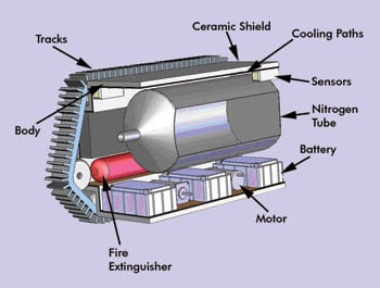
Figure 3. Illustrated here are the inner workings of the fireproof firefighting robot.
Figure 3 shows the inner structure where the robot is actuated with electrical motors and driven with tracks. The energy required by the electrical system is provided by two gel-type batteries. The liquid nitrogen tube is used for the active cooling system, and the fire extinguisher tube is deployed at critical times to help any survivors. The outer shell is covered by ceramic tiles for insulation, and the inner layer is used for passing the liquid nitrogen for cooling purposes. The sensors are used both for navigation and for understanding the fire environment.
Use of photonics in fire
Sensors will be used especially in the navigation system, which is the most innovative part of this research. The earlier designs of firefighting robots always considered the robot as a means to extinguish fires. The effect of the heat, smoke, humidity, and infrared and UV light were not considered.
In this project, the robot will have a sensory system to detect the source of the fire inside the affected zone. The system includes a laser distance sensor and an infrared temperature sensor, both of which are pointed to target objects and rotated and tilted to scan the fire area to measure the temperature of the objects and the distance to the robot. In this way, a 3-D heat-distance map spanning 5 m of the fire zone is generated. To stop any possible echoing of the laser signal emitted from the fire zone itself, the signal is pulse-width modulated to eliminate the effect of the saturation from the smoke and vapor. The infrared sensor has a thermal sensitivity of 0.1 °C at 25 °C, which makes it easy to distinguish burning objects from fire victims.
UV light sensors, such as Hamamatsu’s UVTRON 2868 flame detector, will be used as a backup to the laser infrared sensor combination system.
Later, this type of system can be integrated into human firefighters’ gear, enabling firefighters to position themselves inside a fire zone and to understand fires better and more easily.
In conventional firefighting procedures, a firefighter uses a thermal camera to measure the fire zone. However, such measurements must be taken outside the building because excessive temperatures prohibit the firefighter from entering. This research will result in the creation of a robot that can withstand high temperatures. Control and cooling subsystems will allow the robot to work in these rough conditions.
How it works
Control system: The control system will allow the robot to use the navigation system as well as the sensory and cooling systems. A Kalman filter will be included to analyze the sensor data. When the robot is working in the fire zone, the laser and infrared sensors might not work reliably because of the dynamic environment (in which surrounding objects are burning or falling) and because of smoke generated by burning objects. Given these conditions, data from the sonar, UV and inertial navigation sensors will be blended, and any sensors producing errors will be eliminated. The position, direction and heading of the robot will be computed from viable data. To collect information on the fire zone, the robot will be controlled remotely and will employ a microphone and oxygen, carbon dioxide and explosive gas sensors as well as the CCD camera.
Cooling system: To withstand high temperatures, the firefighting robot will have both passive and active insulation. The passive insulation is achieved by using rock wool on the surface of the robot. Even though the passive insulation slows down the heating inside the robot, the shaft connecting the motors to the tracks forms heat bridges. Liquid nitrogen will be used to stop the heat transfer through this shaft. The nitrogen is kept under pressure inside the tank, but when it is released onto the shaft, it comes to atmospheric pressure and reaches a temperature of –196 °C. To avoid any brittleness, the evaporating nitrogen is guided along the shaft toward the tracks. At the same time, the nitrogen is passed between the copper plates under the surface to slow the heat transfer occurring through the surface of the robot.
The cooling system design for the second-generation firefighting robot is well under way, and we hope to be able to test the new prototype after December because testing is easier in colder weather. With the help of this robot, the effective time inside a fire can be increased, the fire can be mapped, and survivors can be found. Later, the technology may be adapted to the equipment of firefighting personnel so they can work close to fire more easily.
Meet the author
Dr. Emin Faruk Kececi is a project manager at Otokar Otobüs Karoseri Sanayi AS in Arifiye, Turkey. He was part of the group developing the firefighting robot at the Izmir Institute of Technology. He may be contacted at [email protected].