Fiber Polarizer Utilizes Birefringence in Photonic Crystal Fiber
Breck Hitz
Today's fiber optic systems, such as fiber lasers and fiber-based telecom networks, are often forced to use a combination of fiber and bulk optical components because many optical functions, such as polarizers, couplers, filters and mirrors, cannot be readily implemented in fiber. The disadvantages of such hybrid systems include their lack of physical robustness and the optical loss associated with coupling optical power from a fiber into a bulk component and back again.
To overcome such problems, researchers in laboratories around the world are developing all-fiber components that mimic the functionality of traditional bulk optical components. Fiber Bragg gratings, for example, can serve as mirrors and wavelength-dependent filters.
It's been more challenging to fabricate polarizers, which separate light into two orthogonal polarizations, in an all-fiber device. Early attempts have relied on compound semiconductors or on naturally birefringent materials such as LiNbO3 to provide discrimination between the two polarizations, but these polarizers are complex and difficult to fabricate. Recently, scientists at Tsinghua University in Beijing proposed a novel, all-fiber polarizer based on the unique properties of photonic crystal fibers. Taking advantage of the fact that many properties of photonic crystal fibers -- including birefringence -- can be tailored to suit the designer's need, they have designed a dual-core photonic crystal fiber that couples one polarization, but not the other, between cores.

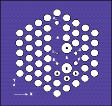
Figure 1. The dual-core photonic crystal fiber polarizer was designed to couple light of only one polarization from one core to the other.
A cross section of the proposed polarizer is shown in Figure 1. It's based on a triangular lattice of airholes running the length of the fiber, with a lattice spacing of 2 µm. The two cores, designated A and B, are formed by the absence of two airholes (core A) and one hole (core B). Moreover, the diameters of the holes in the vicinity of the two cores -- designated 1, 2, 3, 4, 5 and 6 in the figure -- are selected to produce the desired effects.
Birefringence created
The asymmetry of the cores causes them to be birefringent -- that is, to have different effective refractive indices in the X- and Y-directions. One can designate the X- and Y-indices of core A as nAx and nAy, respectively, and, similarly, the indices of core B as nBx and nBy. The design of the fiber polarizer is such that nAx is almost exactly equal to nBx, so that the propagation constants of the X-polarizations in the two cores are almost identical.

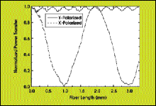
Figure 2. Calculations show that if light of both polarizations were coupled into core A, the vertically polarized (Y-direction) light would remain in core A, but the horizontally polarized light would be coupled back and forth between core A and core B.
Thus, the phase-matched X-polarization waves in the two cores can easily couple energy back and forth. But because the propagation constants for the Y-polarizations in the two cores are quite different, no coupling between them is possible.
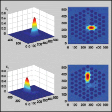
The Beijing scientists' simulation assumed that light polarized at 45° to the X- and Y-axes was coupled into core A, and it predicted the behavior that is illustrated in Figure 2. Light in the Y-polarization remained in core A, but light in the X-polarization coupled back and forth between the two cores as it propagated down the fiber. The trick was to make the photonic crystal fiber 0.995 mm long, so that all the X-polarized light coupled into core B at the end of the fiber (Figure 3).

Figure 3. Numerically calculated field patterns of both polarizations at the end of the 0.995-mm-long polarizer are shown. The horizontally polarized (X-direction) light is coupled back and forth between the cores, and the vertically polarized light is trapped in core A.
Numerically, the scientists calculated extinction ratios greater than 20 dB at the design wavelength in both polarizations for their 0.995-mm fiber polarizer. They also calculated a relatively large bandwidth, noting that an extinction ratio greater than 13 dB could be maintained from 1.50 to 1.58 µm.
They believe that this is the first time anyone has proposed an all-fiber polarizer in a single-material glass waveguide.
Published: September 2004