Dr. Mordechai Gilo, Ophir Optronics Ltd.
Applying new diamondlike carbon multiple-layer coatings to front-surface forward-looking infrared lens assemblies drastically reduces the Narcissus effect without compromising durability.
In Greek mythology, the hunter Narcissus was renowned for his beauty, and exceptionally proud of it: He disdained all who loved him. When Nemesis saw this, he attracted Narcissus to a pool where he saw his own reflection in the waters and, not realizing it was merely an image, fell in love with it. Every time he tried to drink water from the pool, the image vanished; unable to leave the beauty of his reflection, Narcissus died of thirst.
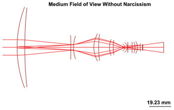
Figure 1. A ray tracing of a zoom assembly in medium field of view. The aperture is wide, and a small percentage of rays are normal to the front surface. Images courtesy of Ophir Optronics Ltd.
In IR cameras, the effect of a detector’s reflection on the detector itself is named after Narcissus. This reflection usually is related to the front surface of the lens assembly and is enhanced if the detector is cooled. In a fixed-focal-length assembly, the surface can be designed to eliminate this effect, but in a zoom-lens assembly, the effect is hard to eliminate.
Figure 1 shows the ray tracing of a zoom assembly in medium field of view (MFOV) compared with the assembly in wide field of view (WFOV) shown in Figure 2. In the first case, the aperture used is wide, and there is a small percentage of rays that are normal to the front surface. In the WFOV case, the aperture is much smaller and the number of rays that are normal to the surface is much greater.
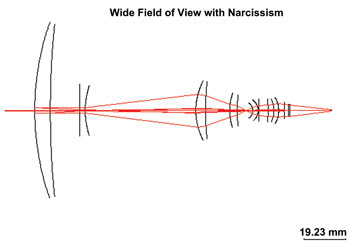
Figure 2. A ray tracing of a zoom assembly in wide field of view. The aperture is much smaller than that of Figure 1, and the number of rays normal to the surface is much higher.
The magnitude of the effect is directly influenced by the reflectance of the antireflection (AR) coating of the front lens. The front lens usually has to withstand the harsh environmental requirements of an external part. The most suitable coating is a hard carbon (HC) or diamondlike carbon (DLC) coating.
DLC coatings
The standard DLC coating is a single layer of carbon atoms with a mixture of SP3 (diamond) and SP2 (graphite) bonds. The SP3 bonds are extremely hard, and the SP2 bonds are soft. The combination of these bonds results in an extremely durable layer that adheres well to Si and Ge substrates. The index of refraction is about 1.9, which is a good optical match to these high-index substrates.
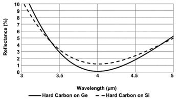
Figure 3. Theoretical reflectance of an HC single layer on Si and Ge substrates: Average reflectance at 3 to 5 µm is ~3.2 percent on Ge and ~3.4 percent on Si. This is too high and results in a noticeable Narcissus effect.
Reflection and tranmittance graphs in the 3- to 5-µm region are shown in Figures 3 and 4. This coating has excellent durability, but the average reflection of 3.2 to 3.4 percent at the 3- to 5-µm region is too high, resulting in a noticeable Narcissus effect.
There are many ways to produce DLC coatings. In chemical vapor deposition (CVD), a chamber contains two electrodes, one connected to a radio frequency voltage source and the other grounded. When argon is introduced, plasma forms as a result of the high voltage. When a carbon-rich gas such as methane, butane or acetylene is introduced, the plasma process decomposes the gas and accelerates the carbon atoms toward the substrate, where the DLC layer is formed (see Figure 5). This is different from the standard physical vapor deposition (PVD) process of evaporation by direct heating.
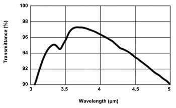
Figure 4. Experimental performance of a single HC layer on Si substrate: Average transmittance at 3 to 5 µm is 94.2 percent.
A new type of coating – low-reflection hard carbon (LRHC) – from Ophir Optronics Ltd. is a multilayer coating with a DLC overcoat layer designed to have a low reflection. The design considerations were (see Figure 6):
1. A dielectric layer with either a Si or Ge top layer would be coated in a PVD coating chamber.
2. The DLC layer would be added in a plasma-enhanced CVD chamber.
3. The DLC layer thickness had to be minimized to reduce internal absorption but to maintain a minimal thickness to achieve the required durability.
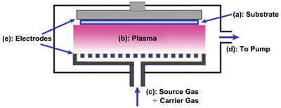
Figure 5. Radio-frequency (RF)-enhanced CVD process. One electrode is connected to an RF voltage source; the other is grounded. At the introduction of Argon, the high voltage causes plasma to form. With carbon-rich gases such as methane, butane or acetylene, the plasma process decomposes the gas and accelerates the carbon atoms toward the substrate to form the DLC layer.
Experimental results
For the 3- to 5-µm region, the preferred substrate for an external lens is usually Si, mainly because of its hardness and low price. With an LRHC coating on Si, shown in Figure 7, the average reflectance achieved in the 3.5- to 5-µm region was 0.26 percent. The average transmittance achieved was 98.5 percent, shown in Figure 8.
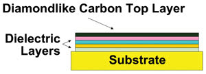
Figure 6. New coating concept of a multilayer stack with a DLC upper layer.
For the 8- to 12-µm region, several coatings on Ge, ZnS and ZnSe substrates were designed with an HC top layer to withstand severe durability requirements. The theorized performance of similar designs on these substrates is shown in Figure 9.
Experimental results for a Ge substrate are shown in Figures 10 and 11. The average reflectance in the 8- to 11.5-µm range was 0.62 percent, with average transmittance of 94 percent in the same region.
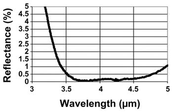
Figure 7. Experimental reflectance results for an LRHC design on Si for the 3- to 5-µm region. The average reflectance achieved in this region was 0.26 percent.
Reduction of Narcissus effect
Several AR coatings were applied on the front Si lens of a 15- to 300-mm zoom assembly.
A lens with a single-layer DLC and a typical average reflectance of 4.8 percent in the 3- to 5-µm region was compared with an LRHC coating with a typical average reflectance of 0.5 percent, both in the WFOV state.
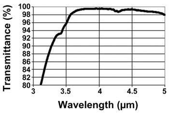
Figure 8. Experimental transmittance results of a Si window. The back side is coated with an AR coating with an average reflectance of 0.2 percent. The average transmittance achieved was 98.5 percent.
In the first case, the effect was noticeable, while in the second case, the effect was not seen (see Figures 12 and 13).
The above designs show that a multilayer coating with a DLC top layer has good potential for external surfaces. Several designs were demonstrated for a Si substrate in the spectral region of 3 to 5 µm and for a Ge substrate in the 8- to 11.5-µm spectral range.
Other designs show that this concept can be applied to ZnSe and ZnS substrates.
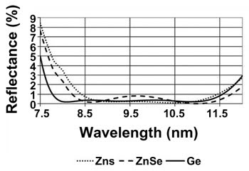
Figure 9. Theoretical performance in the 8- to 12-µm region of multilayer coatings with a DLC top layer on Ge, ZnSe and ZnS substrates.
All the coatings passed the durability tests required of a DLC coating (humidity, severe abrasion, salt immersion, salt vapor and acid corrosivity), including the 5000 revolutions wiper sand test. They can be applied on lens assemblies for high external durability and low Narcissus effect.
Every system designer knows that in AR coatings, there is always the trade-off between the best optical performance and the highest durability. These coatings can substitute the system front surface coatings, while ensuring the required low
reflection. They also will provide the highest known coating durability and could be developed for more than one spectral region for a variety of applications.
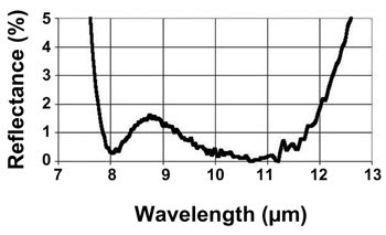
Figure 10. Measured reflectance results of LRHC coating on Ge. The average reflectance in the 8- to 11.5-µm range was 0.62 percent.
Meet the author
Dr. Mordechai Gilo is process development manager for R&D and engineering at Ophir Optronics Ltd., a Newport Corp. brand, in
Jerusalem; email: [email protected].
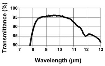
Figure 11. Measured transmittance results of LRHC coating on Ge. The back side was coated with an AR coating that had about 0.3 percent average reflectance in the 8- to 11.5-µm region. The average transmittance was 94 percent in this region.

Figure 12. Lens assembly with a single-layer HC front lens in wide field of view. The central circle and one ring are noise from the Narcissus effect.

Figure 13. Lens assembly with an LRHC coating having an average reflectance of 0.5 percent, with the same field of view as in Figure 10. The Narcissus effect is eliminated.