High-accuracy lens measurement system holds the answer
Stephen D. Fantone and Daniel G. Orband, Optikos Corp.
In today’s global economy, optical components and systems are purchased from sources around the world,
so the need for performing incoming inspection rapidly and efficiently has never
been greater. Frequently, optical components that are sourced from domestic sales
firms are actually manufactured elsewhere in overseas facilities with minimal quality
control processes, metrology personnel and equipment.
A production facility or quality control lab requires inspection
equipment with broad applicability and flexibility, typically operated by a technician.
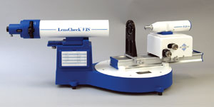
The LensCheck Bench from Optikos Corp. (Figure 1) is a step toward providing a cost-effective
test platform for evaluating the performance of visible and near-IR optical systems
over a broad range of test conditions. With space at a premium in most manufacturing
and testing facilities, the compact device’s tabletop footprint is less than
4 sq ft, allowing it to be located on a standard laboratory table; a floating table
is not required. The system is portable and can be readily relocated and reconfigured
within a few minutes for testing.

Figure 1. The LensCheck bench comprises a 58-mm clear-aperture collimator, a rotary stage
and an image analyzer. Images courtesy of Optikos Corp.
The LensCheck Bench allows an operator to easily confirm the basic
performance of an optical component or system and to assess more complicated performance
requirements. The light source and multiposition filter wheel enable lens and system
testing using the spectral distribution encountered in actual use. It is not restricted
to specific wavelengths and enables characterization of the various chromatic effects
(such as longitudinal and lateral color or spherochromatism) that simply are not
available with monochromatic testing techniques.
Frequently, catalog optical components have tolerances in focal
length and centration accuracy that require evaluation of first-order and imaging
properties of the lens before it is installed in a system. For example, manufacturers
of medical diagnostic equipment frequently incorporate off-the-shelf components
including singlets, doublets and microscope objectives. Before mounting and aligning
such components into a high-value assembly, it is prudent to confirm the performance
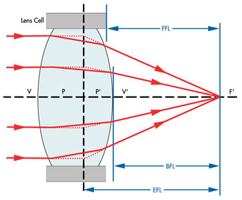
of such components by measuring their first-order properties: effective focal length
(EFL), back focal length (BFL), flange focal length (FFL) (Figure 2) and on-axis
imaging performance (modular transfer function [MTF], resolution and/or spot size)
under test conditions simulating their actual use.

Figure 2. This diagram shows several first-order optical parameters.
To space components properly to achieve desired magnification
and total track between object and image plane, it is essential to know the precise
focal length and principal point locations in a lens relative to mounting surfaces.
Thus, the ability to accurately measure parameters such as focal length, BFL and
FFL greatly simplifies and accelerates the assembly of these systems, making the
manufacturing process more predictable and deterministic.
This quick check assures that a component achieves its nominal
performance and may safely be incorporated into a larger optical assembly.
Often, a quick inspection of the on-axis image blur determines
that the blur shape is asymmetrical, meaning that the lens has a centration error
and must be rejected. If a more quantitative metric is desired, the blur spot size
(in X and Y) and the measured MTF can provide precise measurement of astigmatism
– information that can be used to evaluate the impact on overall system performance.
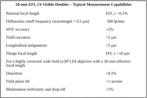
How accurately can we measure these lens parameters? Consider
a 50-mm-focal-length f/4 well-corrected, well-centered doublet in the visible spectrum
(See Table 1).

Note that these capabilities scale with f number and focal length
so that highly corrected faster systems can be measured to higher accuracy, and
slower systems to lower accuracy. Typically, longitudinal aberrations in a highly
corrected system may be measured to a fraction (<1/5)
of the longitudinal diffraction depth of focus, allowing one to assemble a system
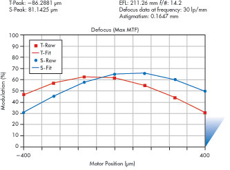
with confidence that the predicted performance will be achieved. A typical through-focus
MTF curve of a lens exhibiting moderate astigmatism (167 µm) is depicted in Figure
3. This lens, with an f number of 14.2, has a diffraction depth of focus (±2
λ f/#2) of approximately ±200 µm.

Figure 3. A typical mid-frequency MTF curve readily quantifies system astigmatism.
To obtain results to these accuracies, the lens under test must
be properly fixtured and aligned relative to the optical bench axes. Also, all slides
are instrumented with glass scale encoders so that derived calculations such as
focal length (EFL = image shift/tan [Θ]) can be performed to the requisite accuracy.
Accurate measurement of MTF requires that stray light in the system be captured,
and therefore use of a camera with an extended bit depth and dynamic range is essential.
To achieve high throughput, patented use is made of VideoMTF software to measure
blur spot size and MTF using real-time video capture.
We have seen a number of highly unusual systems requiring characterization
over very wide fields (beyond ±90°) or very low f numbers. The Optikos
LensCheck Bench allows a user to test lenses over fields of view extending to ±105°.
The high-quality re-imaging objectives enable testing of lenses with numerical apertures
as high as 0.8. In specialized cases using an immersion objective as part of the
image analyzer relay, it has been possible to test optical systems that are part
of fluorescence imaging systems with numerical apertures approaching 1.5.
While in many cases an optical system is used at infinite conjugates,
numerous optical systems are intended to relay images and must be tested at their
designed finite conjugates. For example, a short 4:1 finite conjugate relay system
should be tested at the actual finite conjugates of use. In most cases, the design
performance at infinite conjugate would be substantially degraded. Optikos has developed
the ability to perform these tests and to characterize distortion and other field
aberrations to extreme precision by incorporating high-accuracy encoders into the
image analyzer stages. Distortion accuracy of less than 0.1 percent can be obtained
over a 100-mm field, though it is usually limited by the distorted blur shape formed
by the lens.
All of this is accomplished through the use of a USB-based motion-control
system working closed loop with encoders on multiple axes. The VideoMTF software
assures a level of metrology accuracy and precision not previously available at
this price point and unit size.
Collectively, the Optikos LensCheck Bench brings a new level of
capability to production facilities and allows technicians to make measurements
that otherwise would have to be made by development engineers. This enables manufacturers to qualify every incoming product quickly and reliably, while greatly minimizing
the costs and risks of substandard complete assemblies.
Meet the authors
Daniel Orband is the director of engineering at Optikos Corp.
in Wakefield, Mass.; e-mail: [email protected]. Dr. Stephen D. Fantone is the
founder and president of Optikos; e-mail: [email protected].