John Wingerd, Siskiyou Corporation
Several different technologies offer a range of performance options within the confines of an optical microscope for patch-clamp studies,
intracellular recording and other demanding experiments in electrophysiology.
Electrophysiology encompasses the measurement and analysis of transient ion flows and resultant voltage changes across cellular membranes (e.g., sodium ion channels that enable nerve-cell signal transmission).
A key but often unheralded component of these experiments is the micromanipulation system used by the researcher to maneuver the micropipettes or other electrodes. These micromanipulators must move and position a pipette/electrode with micron-level precision and stability. However, the spectrum of commercial and research applications has a range of requirements in terms of performance, features, cost, speed and flexibility. To optimally meet the needs of each of the diverse uses, equipment suppliers have developed a range of micromanipulator technologies that can be combined in modular ways. This provides the right mix of degrees of freedom, coarse and fine control, and manual and automated adjustment that each user requires.
Each micromanipulator technology offers a unique set of advantages. In this article, we will compare three of them and examine how each best meets the needs of specific applications.
Voltage and patch clamps
The simplest way to study ion flow and resultant electrical potential changes across a membrane is to place an electrode on either side of that membrane. The oldest – and most popular – method is to insert a micropipette inside a cell, neuron or other study target. Electrical measurements are then made relative to a reference electrode located in the external buffer in which the sample is bathed.
Depending on the cell type, the current flow can be extremely small (picoamp to nanoamp regime). To overcome noise and to quantitatively measure the current, specialized circuitry maintains a set potential difference between the two electrodes (i.e., to clamp the voltage difference). This is often chosen to be a zero difference – that is, temporarily depolarizing the membrane. The transient currents required to maintain this difference are recorded as a function of time as the ion channels in the membrane respond to this externally induced perturbation in the potential across it.
The term “patch clamp” refers to the most common experimental configurations, where the aperture of a micropipette is used to define a test area or membrane patch, as shown schematically in Figure 1. A low level of suction draws the membrane into the aperture and makes an ion-impervious seal. By using a small micropipette aperture, a patch or membrane containing anything from just a single ion-channel protein (typical pipette diameter <0.3 µm) up to hundreds of ion channels can be sampled. “Cell attached” measurements then can be made by depolarizing and polarizing the patch and by observing the transient current flows that characterize the ion channels being studied.

Figure 1. (a) The pipette is brought into proximity of the cell wall. (b) In simple “cell attached” patch-clamp studies, it is placed over a small area of membrane, and suction is applied to make an ion-impervious seal. (c) In some “inside out” studies, the pipette is retracted to separate some of the membrane in the “inside out” configuration. The number of channels in the sampled patch can vary from one to hundreds. Images courtesy of Siskiyou.
Alternatively, the suction can be increased to break the membrane and to physically remove the patch for isolated study. Clever tricks allow it to be studied from either side – in “inside out” or “outside in” configurations. As another option, the patch can be more abruptly torn by suction so that the cell contents and pipette interior are at least temporarily contiguous. This allows “whole cell” recording in an alternative configuration to piercing the cell membrane with a pipette/electrode.
Many variants of these basic methods allow researchers to target intracellular membranes or to make measurements on specific intracellular volumes. All are dependent on precise X-Y-Z positioning of one or more pipette electrodes. Specifically, they require the ability to move the pipette along its axis direction with precision and control on the micron scale, and with minimal lateral uncertainty or errors.
Today, numerous technological approaches (e.g., mechanical, electrical and hydraulic) to this challenge exist, as well as supplier-specific implementation details. The ideal choice for a given application is determined by matching the performance specifications to the requirements of the experiments, as well as a few practical factors and cost considerations. Typically the complete solutions are modular so as to optimally combine one or more axes of lower-cost coarse positioning/adjustment with the requisite amount of fine positioning. (Performing experiments with all-fine adjustments throughout the necessary range of travel would be unnecessarily and prohibitively costly.)
Huxley-style flexures: tried and true
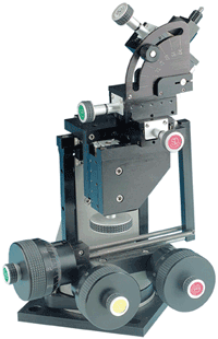
Electrophysiology pioneer Andrew Huxley’s original experiments were performed using all-mechanical micro-manipulation systems. These were based on flexures where the position is controlled by driving the pipette holder – usually mounted on a head stage – via manually turning a fine-pitched leadscrew against resistance provided by a metal flexure. This type of simple, time-proven mechanical flexure combines modest resolution with low cost. A commercial example is Siskiyou’s MX300 series, which uses manually driven 100-threads-per-inch (TPI) screws and ball-bearing translation stages to deliver a resolution of <1 µm.

Figure 2. Traditional Huxley-style mechanical micromanipulators are based on flexures and usually incorporate dial-like knobs for manual adjustment. With this modular MX310L system from Siskiyou, coarse adjustment is provided by incorporating lower-resolution stages at the top of the assembly. Simple pipette replacement is supported by a rotary stage at the base of the system with a hard mechanical reference stop.
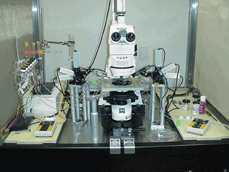
Experiments typically are performed under an optical microscope, often with less than 2 mm of working distance under the objective. As a result, the probe has to
be brought into the sample within a very limited, angular range. To enable simple probe/pipette replacement under these constraints, the complete assembly incorporates a low-resolution rotation stage equipped with a hard (settable) mechanical stop. This allows the head stage to be able to swing out of the experimental position and then to be returned with kinematic fidelity. Coarse adjustment is optionally provided by mounting a five-axis stage module on top of the fine flexure motion system.
These axes are also driven manually, but with 20-TPI screws. Along the critical pipette axis, the end result is 20 mm of coarse motion and 2 mm of fine motion.
These Huxley-style flexures are optimized primarily for teaching laboratory applications, where typical experiments require lower resolution and are targeted at larger cells (50 µm to 1 mm in diameter). Compared to other micromanipulator systems, they deliver the robust durability and low cost needed for a teaching lab, albeit in a somewhat bulky format.
As with all micromanipulators for electrophysiology applications, it is important that the rotational axis of the motion is perfectly aligned with the electrode/
pipette on its accompanying head stage. At the same time, it is advisable to electrically isolate the pipette and head stage from the micromanipulator
assembly. In principle, both plastics and ceramics could be used for this isolation. However, we have found that using a solid cylindrical ceramic rod for this mounting connection minimizes thermal drift and provides maximum rigidity.

Figure 3. In electrophysiology studies, the confined experimental space under a microscope objective means that the micropipette electrode(s) only can be introduced in a narrow range of angles.
Hydraulics: smooth and fast
Engineers have long known that some of the smoothest continuous motion can be driven using hydraulics. Here liquid is forced into or out of an expandable, sealed enclosure that permits motion in a single axis, such as a bellows or a cylinder and piston. An example is the MX6000 series from Siskiyou, which combines a metal bellows for longevity and durability with a crossed-roller bearing translation stage. Crossed-roller bearing stages are widely used in demanding photonics applications because they deliver precise linear motion (eliminating play like pitch and yaw) with extremely long lifetimes. As with the flexure actuators, motion is manually controlled by the rotation of a large dial. The fine-positioning adjustments on the three axes – probe (X), Y and Z – use ultrafine 127-TPI adjustment screws to deliver
5 mm of linear motion with 0.5-µm resolution. Also, a coarse-positioning system is optionally integrated into the complete modular assembly, as well as an optional rotary stop for accurate repositioning after pipette exchange.
A key design consideration for any hydraulic system is the choice of fluid. For example, viscosity will directly impact system responsiveness. Another important factor is thermal expansion, as changes in ambient temperature can cause the liquid to expand or contract, which potentially may result in minor positional drifts. Overall we have found that water is the best liquid for actuators for electrophysiology; it delivers the requisite responsiveness but with two to three times lower thermal expansion than that of typical hydraulic oils. The result is a drift of <2 µm per hour under nominal, constant temperature conditions. However water can be problematic when using nylon and related plastics because these organics slowly absorb water. For this reason, Teflon tubing is used to connect the drive and output bellows. Nonetheless, we recommend flushing and refilling every two years to maintain specified performance levels.
The responsiveness of hydraulic systems means that they are well-suited to demanding research applications with typical cell diameters around 10 µm or less. They often represent the best solution for intracellular recording, where an abrupt impaling action is needed to pierce the cell with a sharp electrode. Generally, these types of experiments are less than 20 minutes in duration, so minor long-term drift is not an issue. The ability to make rapid piercing movements is the reason why hydraulics often are preferred for microinjection and similar applications. As one example, they are widely used by in vitro fertilization laboratories to perform genetic material transfer, as well as fertilization.
DC servos: highest stability and lowest noise
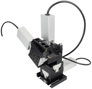
High-end micromanipulators offer higher resolution as well as automated (i.e., electronic) control, rather than solely manual adjustments. There are several types of electronic actuators widely used to drive stages in all kinds of photonics applications, including stepper motors, DC servos and piezoelectrics. At Siskiyou, we use only DC servos in our MX7000 series because these best meet the needs of patch-clamp studies, which form the majority of the electrophysiology market’s high-resolution segment. Also, because they are intended for the highest-resolution applications, they are paired with crossed-roller bearing stages and assembled as four-axis micromanipulator modules.

Figure 4. Higher-performance micromanipulators provide automated (push button/software) positional control by incorporating electronic actuators. Siskiyou’s MX7600 system is based on DC servos that produce zero electromagnetic interference when stationary, unlike piezos or microsteppers.
As a result, a single DC servo driver moves the pipette smoothly along its axis. In contrast, some commercial electronic axis control systems synthesize a “virtual” probe axis; they iterate X and Z motion in predetermined ratios only. In that case, the probe doesn’t go straight into the target but enters the cell by stepwise iterating the X and Z axes. The system also can include a low-resolution rotary stage to set a micron-accuracy hard stop for simple pipette replacement.
Patch-clamp studies are the most electronically demanding of all electrophysiology procedures because they usually involve the smallest signals; a small patch may contain just a single ion-channel protein complex. In fact the signals are so small that no external electronic noise sources can be allowed to reach the amplifier circuitry. Although the pipette/electrode and amplifier head stage are electrically isolated by a ceramic connector rod, the intimate proximity of the actuators to the experiment means that even minor free-space electromagnetic interference must be avoided. This is a potential problem for steppers (especially when microstepping) and piezo systems, where current is continuously drawn to maintain position. This ongoing current draw also means these systems create unwanted heat, even when stationary
(i.e., during the measurements). Thermal drift is always the enemy of precision positioning.
In contrast, a DC servo system draws current only when it is moving. In fact, the power supply can be completely disrupted without causing any shift in position. As a result, DC servos produce no electromagnetic interference when stationary and offer the lowest drift of any electronic actuator.
The term “servo” refers to the fact that these actuators can be moved directly or in response to position sensor feedback. Direct push-button control delivers spatial resolution of 0.1 or 0.2 µm, depending on the choice of system controller. Also, in closed-loop operation using integrated optical encoders for servo feedback, these systems deliver even higher resolution. These encoders also support high-speed motion – up to 1.7 mm/s.
Meet the author
John Wingerd is senior mechanical engineer at Siskiyou Corporation in Grants Pass, Ore.; email: [email protected].