New assembly and thin-film coating techniques are producing optical components for high-energy applications.
Emily Kubacki, Precision Photonics Corp.
As laser energies have increased throughout the years, the selection of appropriate polarization components has become more limited. Until recently, if a system was running greater than about 1 J/cm2, the only options were air-spaced beamsplitter cubes or Brewster angle plate polarizers, both of which require fairly complicated beam paths and alignment.
Fortunately, as coating technologies and assembly techniques have improved, so have the selection and quality of high-energy polarizers. Three types of components using new designs and advanced techniques in both assembly and thin-film coating have become available for high-energy applications from the UV through the visible and NIR: epoxy-free beamsplitter cubes, single-element crystal polarizers and non-shifting thin-film plate polarizers.
For high damage threshold applications requiring the optical path lengths of the orthogonally polarized beams to remain equal, polarizing beamsplitter cubes are the obvious choice. An idyllic cube would separate the polarized beams by 90° for easy alignment and would be manufactured without the use of epoxies or optical cement, which can outgas or can absorb or scatter input light, resulting in separation of the components or catastrophic laser damage.
Fabrication of high-energy cubes meeting these criteria can be accomplished through epoxy-free bonding techniques such as optical contacting and chemically activated direct bonding. Although significant-ly more costly up front, the advan-tage of epoxy-free components for high-energy applications is clear.
Adhesive-free bonding
Optical contacting is a room-temperature process dating back to the 1930s in which two well-polished right-angle prisms are coated and then physically pressed together to achieve an adhesive-free bond. Although typically performed using clean, dry glass or coated components, a small amount of isopropyl alcohol also can be used at the interface to permit minor adjustments to the alignment of the components while the alcohol evaporates.
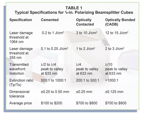
This method produces an optically transparent assembly that usually is edge-sealed along oversize bevels to increase the overall strength and lifetime of the bond. Beamsplitter cubes, wave plates and mirror assemblies using this production method have been manufactured successfully using fused silica, Schott AG’s Zerodur, crystal quartz and other optical glasses. Typical specifications for various types of polarizing beamsplitter cubes are shown in Table 1.

Chemically activated direct bonding is an alternative to optical contacting that results in more robust bonds and manufacturing flexibility. Unlike more elaborate processes such as diffusion bonding, which uses pressure with highly elevated temperatures applied in a protected atmosphere, chemically activated direct bonding is an adhesive-free process that requires only a cleanroom environment and a skilled technician. After chemical activation, the two surfaces are brought into contact and annealed at material-specific temperatures to form covalent bonds between the atoms of each surface, resulting in structures that can exhibit bulk strength and a zero-thickness bond line at the interface.
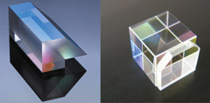
A primary advantage of a direct-bonding technique over optical contacting is that the increased strength of the bond allows processing after assembly, meaning that the bonded parts can be cut, shaped, polished or coated to create highly toleranced or multicomponent assemblies (Figure 1) without the temperature constraints or threat of delamination exhibited by other assembly techniques. Because there is no epoxy, the finished units are compact and thermally stable, exhibiting insignificant levels of absorption or scattering loss at the optical interface.

Figure 1. Multicomponent adhesive-free assemblies can be manufactured via chemically activated direct bonding. Because no epoxy is required, the finished assemblies have insignificant levels of absorption or scattering loss at the optical interface.
Optically contacted and chemically bonded cubes are designed for single laser-line wavelengths from 193 to 2200 nm using multilayer dielectric coatings within fused-silica glass. They are intended primarily for narrowband laser applications where optical path lengths must remain equal, and where transmitted and reflected wavefront quality must be maintained, and/or where laser energies exceed about 1 J/cm2.
By modifying the design of a fused-silica cube to have an internal angle closer to Brewster’s angle, broadband and multiwavelength polarization can be achieved without compromising wavefront, transmission efficiency or damage threshold. The larger internal angle results in <90° separation in the output beams but also expands the possible coating design options to produce cubes with bandwidths of 200 nm or more.
Another way to increase bandwidth of the polarizing coating is by using a higher-index glass substrate such as flint glass. The higher-index glass, in combination with standard dielectric coating materials, yields results similar to those of broadband cubes but without the disadvantage of having to align additional optical components in the system at odd angles. Because they are epoxy-free, these beamsplitter cubes still withstand high laser energies of at least 4 J/cm2 over bandwidths of greater than 300 nm in the visible or NIR wavelength regions, while exhibiting high extinction ratios and good transmitted wavefront properties.
Flint glasses
SF2, SF10 and SF11 are some of the more common and readily available flint glasses. Although comparable in cost to fused silica, the optical and mechanical properties of these glass types can be a hindrance to their manufacturability. These glasses are optimized to transmit in the visible region from 400 to 800 nm, with some extended transmission into the near-UV and NIR.
For long optical path lengths such as those through a 20-mm or 1-in. cube, even a small percentage of absorption is too much, making the materials ineffective for beamsplitter cubes below about 420 nm. In addition, many high-index flint glasses have a large coefficient of linear thermal expansion as well as a low resistance to alkali and acids. Consequently, they require different polishing and assembly materials and techniques than those commonly used with silica and crown glasses.
Single-element crystal polarizers are not yet widely available, but initial designs indicate that they have significant potential as high-energy broadband polarizers. Anisotropic crystals such as alpha-barium borate (α-BBO), yttrium vanadate (YVO4), rutile (TiO2) and lithium niobate (LiNbO3) can be used alone or in combinations of two to three prisms for lasers with beam diameters up to 10 mm.1
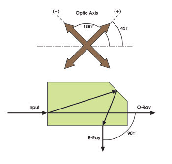
In a single-element crystal polarizer, the birefringence of the crystal creates two orthogonally polarized beams when unpolarized light enters the crystal in a direction non-parallel to the optic axis. By utilizing total internal reflection and altering the direction of the optic axis within the crystal, the mechanical angles of the prism components can be designed in multiple ways to optimize the divergence angle and separation of the exiting polarized beams (Figure 2). Employing Brewster angle epoxy-free designs makes nonlinear crystal polarizers promising as low-loss replacements for standard cemented or air-spaced calcite polarizers in many mid- to high-energy laser applications.

Figure 2. A single-element crystal polarizing beamsplitter, using total internal reflection and altering the direction of the optic axis within the crystal, allows the mechanical angles of the prism components to be designed to optimize the divergence angle and the separation of the exiting polarized beams.
Disadvantages of single-prism polarizers include prism anamorphism, or astigmatic image asymmetry, as well as thermal and dispersion dependence on beam angle and spatial position. These drawbacks can be overcome by designing epoxy-free assemblies using two- or three-component combinations of symmetric prisms.2 Correct optimization of the prism angles and air gaps creates beamsplitters in which the orthogonally polarized beams undergo the same number of reflections, resulting in dispersion- and astigmatism-free polarizers that are both compact and thermally stable.
Although more difficult to process than optical glasses such as BK7 and fused silica, the crystal design removes any dependence on thin-film coatings or on optical assemblies, possibly reducing the overall cost of manufacturing them to a price equal to or even below that of other high-energy polarization components. Final performance parameters and specifications have yet to be established, but without cement or complicated coating stacks, laser damage thresholds should be limited only by the bulk material itself.
Plate polarizers
Plate polarizers are used in situations where high laser damage thresholds are required, but the size, performance or cost of a beamsplitter cube is undesirable. Coated thin-film plate polarizers exploit the interference effects within the coating layers to reproduce a pile-of-plates Brewster angle design in a single-component configuration.
Because the coating can be formed on any shape or thickness substrate, plate polarizers can be designed to minimize pulse dispersion and reflected or transmitted wavefront distortion without sacrificing clear aperture or transmission efficiency. A laser-quality plate polarizer designed for 1064 nm can withstand greater than 10 J/cm2 of pulse energy in the transmitted beam (p-polarization, with transmission greater than 97 percent) and as much as 20 J/cm2 in the reflected beam (s-polarization), with typical transmitted extinction ratios exceeding 1000:1.
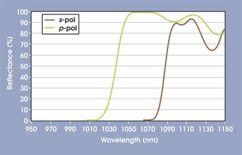
Plate polarizers are available throughout the UV to NIR wavelength regions at either Brewster’s angle (56°) or at 45° (Figure 3). The 45° design is ideal for easy setup and alignment, and it creates orthogonally polarized beams separated at right angles. However, although more complicated to align, Brewster angle polarizers achieve higher transmission efficiency and extinction ratios over a broader acceptance angle than the 45° plates.

Figure 3. A spectral trace of a thin-film plate polarizer designed for 1064 nm at 45° incidence is shown.
Historically, thin-film plate polarizers required angle-tuning during usage. Because of the porous nature of electron beam-deposited coating stacks, environmental changes to humidity and temperature cause a wavelength shift within the coating that can alter the spectral performance of the polarizer at any given wavelength.
Recent advancements in ion-beam-sputtering coating processes have eliminated this effect, making the plate polarizer a more stable and functional component. During ion-beam-sputtering coating, a high-energy ion beam is used in a vacuum to deposit dielectric materials onto a substrate.
Unlike in evaporative or ion-assisted processes, the materials in the coating chamber are deposited at a high average energy, approximately 10 eV, or 100 times their thermal energies. This enables the molecules to form covalent bonds, resulting in thin films with extremely densely packed micro-structures. Consequently, ion-beam-sputtered films are nearly impervious to water vapor, resulting in insensitivity to changes in heat and humidity, even in a vacuum environment.
Throughout the industrial laser, semiconductor and aerospace industries, increased laser energies have continued to push the optical component marketplace to new and higher thresholds. Polarizing beamsplitters have not been excluded from this development; instead, they have utilized innovative designs and techniques to improve and expand upon the products available. Higher damage thresholds, increased transmission and improved functionality are all features of current coating designs as well as readily available optics and optical assemblies for use in today’s applications.
Meet the author
Emily Kubacki is manager of technical sales at Precision Photonics Corp. in Boulder, Colo.; e-mail: [email protected].
References
1. B.L. Davydov and D.I. Yagodkin (2005). Compact prisms for polarisation splitting of fibre laser beams. QUANTUM ELECTRON, pp. 1064-1070.
2. B.L. Davydov (2006). Polarisation splitting of laser beams by large angles with minimal reflection losses. QUANTUM ELECTRON, pp. 473-482.