Marc D. Himel and Jim Morris, DigitalOptics Corporation
Design considerations and fabrication affect performance for a near-IR large-angle homogenizer for use in 3-D sensors based on time of flight.
The field of diffractive micro-optics is playing an increasingly important role in today’s technology, from high-speed data communications to bar-code scanners, and even in one of the world’s most popular gaming interfaces.
Now, advances in the tools available for the manufacture of diffractive optics have opened up additional opportunities in visible and near-IR applications that require very large angular distributions, including virtual keyboards, laser levels, optical touch panels and screens, and 3-D sensing. In many of these applications, laser diodes combined with diffractive optics are replacing LEDs that use conventional collection optics. This helps decrease package size, lower cost and increase wall-plug efficiency.
When the first laser light was produced, Ted Maiman and colleagues probably did not guess that their invention would become ubiquitous in just 50 years. At the time, they considered laser light to be a solution in search of a problem. But today, lasers shape our world in countless ways, and new applications are developed every day. Many of these require advanced manipulation of laser light that can be accomplished only with diffractive optics.
These applications include signal monitoring for today’s high-bandwidth data communication systems, in which a diffractive optic not only couples light from multiple lasers into and out of optical fiber, but also samples a small percentage of the energy to ensure signal power stability; 2-D bar-code readers, which use a frame generator to identify the region of interest; and off-axis illumination that provides resolution enhancement for today’s high-end lithography scanners.
The availability of advanced e-beam and optical lithography tools, originally developed for computer chip manufacturing, has opened the door to a wide range of applications that require very large divergence angles from the diffractive optical element (DOE). To be efficient enough for practical use, these elements require feature sizes equal to or less than the wavelength of light. Two key consumer examples are the laser virtual key-board (such as Celluon’s Magic Cube) and Microsoft’s Kinect 3-D gaming interface, which uses structured light to determine distances.
Technology based on time of flight (TOF) is also being implemented in depth-sensing applications, such as eeDoo’s iSec gaming system and large-area optical touch screens. One advantage of TOF technology is that simpler optics can be used to uniformly illuminate the field of view (FOV) because a structured light pattern is not required. Most TOF systems today use LEDs. However, factors such as lower cost, improved wall-plug efficiency, reduced size and improved depth-sensing performance may drive the adoption of laser-based illumination. This will occur only if micro-optical components can be used to efficiently create the desired far-field light distribution.
Diffractive-based TOF light sources
Today’s TOF systems use multiple LEDs combined with collection optics that produce a circular FOV with a nominal Gaussian intensity profile. To maintain a decent dynamic range for a 3-D camera, the illumination intensity should be held to a 2:1 or 3:1 ratio from center to edge. This requires that a Gaussian profile significantly overfill the FOV. Therefore, more than 50 percent of the light emitted by the LEDs and collected by the lens falls outside the camera’s FOV and goes to waste. This can be somewhat improved if we allow the optics to be made larger, which would also increase the size of an already large assembly (i.e., some TOF systems already use eight or more LED modules).
A typical implementation of a DOE-based illumination system uses a collimated laser beam incident on a computer-generated hologram that has been designed to generate the desired far-field optical distribution. With TOF 3-D sensing, the desired output is to illuminate the field of view of a VGA or megapixel near-IR camera. To uniformly illuminate the sensor over a large 70° x 50° FOV requires correcting the DOE for cosine theta effects, which means redistributing energy to send more light to the larger deflection angles. One advantage of a DOE is that the energy distribution can be optimized, so that the image sensor is uniformly illuminated after light reflects off an object and is reimaged with a low f/# lens. Unlike an LED-based system that illuminates a scene with a circular distribution, the DOE design can be optimized to illuminate the rectangular area within the sensor’s FOV, thus improving wall-plug efficiency.
The shift to a laser-based source also allows the package size to be significantly reduced, which will be necessary when 3-D sensing and gesture control are to be implemented beyond industrial, automotive and gaming consoles, where module size is less critical. Using non-TO-can packaging approaches, such as C-mount or silicon benches, in conjunction with diffractive optics will provide packages with a total height from 1.5 to 3 mm, which are thin enough to fit into the bezel of flat panel televisions, computer monitors, laptop computers and even smartphones.

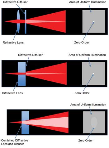
Figures 1-3. Top: A traditional approach for creating a uniform far-field distribution uses a refractive collimating lens in line with a diffractive pattern generator. Center: An all-diffractive approach for creating a uniform far-field distribution. In this example, the collimating lens is on one surface, and the pattern generator is on the second surface. Bottom: By combining the diffractive lens and pattern generator into a single surface, we can optimize the design for efficiency and eye safety. Images courtesy of DigitalOptics Corporation.
The requirements for manufacturing a DOE for this application are challenging. A simple binary design requires features smaller than the wavelength of the illumination source. Without tight control over the lithographic process, it will not be possible to meet the requirements for both efficiency and nondiffracted zero-order energy. If the zero-order energy is too high, the system may not meet eye safety requirements. Although methods are available to reduce the impact of the zero order for this reason, most of these methods further reduce the efficiency of the DOE, thus requiring higher power from the laser. To meet eye safety requirements, DigitalOptics Corp. has developed a process using deep-UV lithography that maintains efficiency while reducing the impact of the zero order.
A key differentiator for this design is the ability to combine different optical functions into a single diffractive optical element. Figure 1 shows a traditional approach for creating the uniform far-field distribution using a refractive collimating lens in line with a diffractive pattern generator. The combined efficiency of the lens (99 percent) and DOE (75 percent) will be approximately 75 percent, sufficient for most applications. One drawback to this system is that approximately 1 percent of the energy will not be diffracted by the DOE and will propagate as a collimated beam into the far field.

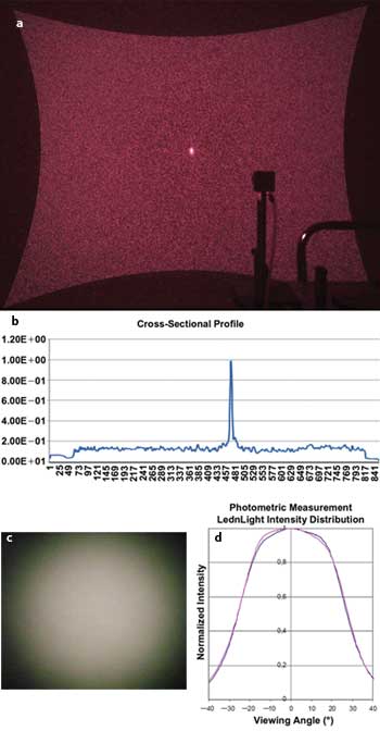
Figure 4. Far-field image (a) and cross section (b) using a laser source, refractive collimating lens and diffractive pattern generator; (c) and (d) represent an LED-based illuminator. Courtesy of LednLight by Gaggione SAS catalog.
For higher-power applications, this poses an eye safety risk. It is also possible to eliminate the refractive lens by substituting a diffractive lens. If the lens is fabricated on one side and the pattern generator on the second side of a single element, one component is eliminated from the system. In this case, the net efficiency will be about 56 percent (75 percent for each DOE surface); however, it will still have an eye safety issue related to the light that is not diffracted by the second surface DOE (Figure 2). It is preferable to combine both the collimating and pattern generation functions into a single surface. This can be achieved with advanced 193-nm lithography tools that can produce sub-200-nm features with 12-nm overlay (a three- to fourfold improvement over i-line lithography). This can produce a single surface design with an efficiency of 75 percent, while the nondiffracted energy diverges for improved eye safety (Figure 3).
To systematically develop this process, DigitalOptics created three designs: a two-phase-level large-angle diffuser that matches the FOV (70° x 50°) of the near-IR camera; a four-phase-level high-numerical-aperture collimating lens combined with a 70° x 50° rectangular diffuser; and an eight-phase-level lens plus diffuser design with features as small as 200 nm.

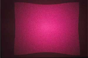
Figure 5. Far-field image based on a diffractive optical element (DOE) that combines the collimating lens with the pattern generator (70° x 50° diffuser). Note the absence of the zero-order energy peak. Courtesy of DigitalOptics Corporation.
The first design was manufactured using i-line process equipment; the other two were manufactured using the 193-nm process. The goal for the first was to optimize the intensity distribution over the camera’s entire field of view. The images shown in Figure 4 represent the far-field distribution imaged with a 14-mm-focal-length lens onto an IR-capable digital single-lens reflex camera. Note the presence of the well-defined edge cutoff and the high zero-order peak in the center of the image on Figure 4a. Although the energy in the zero order is less than 1 percent of the total energy, it still may not be eye-safe because it is well collimated. The cross-section profile in Figure 4b shows good uniform illumination – a significant improvement over the near-Gaussian distribution characteristic of LED illuminators (Figures 4c and 4d).
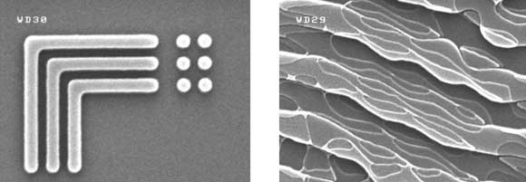
The second design incorporates both the collimating and diffusing function into one DOE and maintains the sharp edge roll-off while diffusing the zero order over a larger angle. Figure 5 shows the measurements for the combined lens and diffuser design. Most of the energy concentrates into the desired rectangular FOV with very little edge roll-off. The zero-order energy is also dispersed and is not observable in the image. Finally, Figure 6 shows the initial results of an eight-phase-level DOE manufactured on a 193-nm lithography tool supporting 200-nm features and 20-nm overlay.

Figure 6. Representative scanning electron microscope images of an eight-phase-level DOE manufactured with 200-nm features. Courtesy of DigitalOptics Corporation.
This work demonstrates all of the building blocks required to manufacture an eight-phase-level diffractive optic that takes the output from a conventional near-IR laser and shapes it into a far-field distribution that uniformly fills the field of view of a near-IR camera while remaining eye-safe. A 193-nm lithography scanner allows a quick ramp of this design to high-volume production for applications in gaming and other human-machine interface systems, such as laptops and flat panel televisions. The incorporation of this design into an integrated micro-optical module will even allow this capability to be introduced into smartphones and thin tablet computers.
Meet the authors
Marc D. Himel is a former senior principal engineer at DigitalOptics Corporation. Jim Morris is senior principal engineer at DigitalOptics Corporation, which is a subsidiary of Tessera Inc.; email: [email protected] or [email protected].