Surface quality is one of the most scrutinized specifications in the optics industry. It is critical that the suppliers and customers have a consistent approach during the inspection process. These guidelines are intended to help ease communication between suppliers and customers for better products and business.
John C. Smith, Rocky Mountain Instrument Co. (RMI)
Surface quality has become one of the most poorly understood specifications in the optics industry. A significant portion of the confusion stems from the two major competing (and largely incompatible) standards, Mil-PRF-13830B, and ISO 10110. Both standards have advantages and weaknesses, and there are even pervasive misconceptions about what they actually say. Further complicating matters, the testing methods used by different shops vary substantially because only a few shops actually use the test methods specified in the standards. It is critical to understand the technical impact, production flow effects, what to ask a supplier, and how to specify and test parts. Using a common language can reduce incoming rejection rates, prevent significant program delays, and ultimately improve customer-supplier relationships.
Why should it matter?
Surface quality is one of the most scrutinized specifications in the industry and, while its significance to any given optic can vary, it is very important that suppliers and customers are on the same page during the inspection process. It is just as essential for customers and their engineers to understand what they are asking for and, much more importantly, why.
Very few suppliers are experts when it comes to every inspection technique. Different standards have different technical advantages and drawbacks, so knowing why a specification has been called out and exactly how critical it is helps customers select and develop their suppliers more intelligently. Similarly, customers that understand their specifications and are willing to make adjustments to their callouts help suppliers better serve and understand their customers, with the ultimate benefit of faster, improved production at lower cost.
Establishing a solid line of communication, as well as mutually flexible relations with suppliers, is always a good idea, but it can be especially important when dealing with complex and confusing specifications like surface quality. Failing to establish this dialog early, on the other hand, can create strong feelings of frustration on both sides, critical schedule delays and potentially serious legal consequences – usually for the customer. Aside from the general business considerations, a minor misinterpretation or bad use of a “bench-mark” comparison can produce an optic that fails to perform in the field, potentially causing harm or preventing an experiment from working.
What are the standards?
There are generally two schools of thought in terms of surface quality: the S/D standards in the US (Mil-Spec or ANSI standards) and the ISO 10110 standard. The former divides surface damage into two categories: scratches, which are self-explanatory, and digs, which are pretty much everything else, including blemishes and bubbles. This is seemingly simple and straightforward, but there is more than one standard, and those standards do not all have the same criteria. ISO 10110, on the other hand, makes no distinction between scratches and digs, unless a distinction is desired. The ISO optical standard, while complicated, is also very flexible. It was intended to eliminate guesswork for inspectors and offer some quantities control to designers. For the most part, it does this but can end up being hard on suppliers without modern inspection equipment.1
Customers need not be “married” to a single standard (unless one is specified for contractual reasons). The key for successful production is for customers to make clear to their suppliers what specifications they are using and where they are being used on their drawings. Suppliers that are serious about their customers will sort out any questions or ask for clarification.
S/D, Mil-Specs, and ANSI
In the Mil-Spec system, scratch and dig values are called out in pairs like 20/10, 10-5, or B-A. Those called out as numbers are referring to Mil-PRF-13830B (or Mil-O-13830), and those called out as letters refer to a common sizing standard spelled out in other technically obsolete Mil-Specs, most notably Mil-C-48497. (For government contractors, the use of these standards for new optics is no longer allowed; however, if the standard appears on an old drawing, it may still be used. Mil-C-48497 is an excellent standard for upper mid-tier and high-end optics. The environmental tests are a little more rigorous than for some other standards but are not overly burdensome for a supplier, and there are no reasons for commercial producers not to use it.)
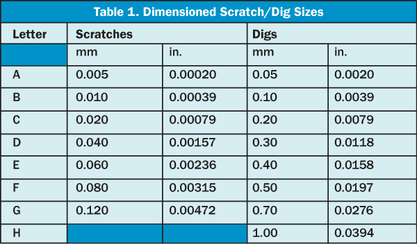
Under the numbered regime, scratches have no associated dimensions. Most customers know this, but some do not. Mil-C-48497, along with several other similar Mil-Specs, does dimension scratches for certain types of optics, mainly opaque optics. Customers using those dimensions will need to specifically call them out as letters. Otherwise, the scratch/dig callout refers back to Mil-O-13830.2,3 Table 1 shows sizes and their correlating letter.

Mil-C-48497 and Mil-F-486163,4
Mil-C-48497 is one of the more common alternatives to Mil-PRF-13830, but customers and suppliers should note that it is being phased out. It and Mil-F-48616 approach S/D from a purely “dimension” point of view and designate each with a letter. The callouts are pretty straightforward, and a good eye loupe or microscope does a decent job when inspecting to this standard. Unfortunately, illumination conditions can have a pretty dramatic impact on what is seen. Many companies use visual standards from the Picatinny Arsenal as comparisons of the lettered S/D standards; however, this practice is not recommended.
Mil-PRF-13830B (Mil-O-13830)2,5
Mil-13830 is the only active Mil-Spec that is concerned with S/D and ultimately the most commonly used; it uses numbers to call out S/D. All numerical S/D callouts refer to this standard or the ANSI equivalent unless the drawing specifically calls out other dimensions, i.e., “scratch size of 20 indicates 20 µm,” etc. The standard refers to Drawing C7641866, a separate document that has gone through numerous revisions to describe scratches. While digs are spelled out within the Mil-Spec, there is no mention of C7641866 in either Mil-O-13830 or Mil-PRF-13830B.
C7641866 describes the test standards and conditions for the scratch and dig standard references produced at Picatinny Arsenal. This drawing is problematic because it was not originally intended to dimensionally define the width of a scratch but rather its apparent brightness under particular test conditions. It currently does this adequately but, in the course of its many revisions, the document has been undimensioned, dimensioned, dimensioned differently, and undimensioned again. Unfortunately, the myth of the dimensioned scratch still persists more than 40 years after the correction was made. In contrast, digs are actually dimensioned, but the test method implied by the reference to the Picatinny standards is visual inspection with the unaided eye. It is typical for producers to do dig inspections visually, so if it is important, make a point of the dimensionality of the dig on the drawing. This is not likely to improve quality, but it will give you a more solid argument if there is a return.6
The general technique for inspecting S/D based on Mil-13830 is to use light propagating parallel to the surface and perpendicular to defects under scrutiny. The ANSI standard goes into specific detail as to how to inspect parts using the cosmetic standards, but it is difficult to know if they apply, and many shops use different techniques. A combination of a high-intensity, movable light source for scratches and digs can be especially effective when inspecting large parts in combination with broad, even light sources for staining. Using a black backdrop can help the inspection, too.
ANSI/OEOSC OP1.002-20097
ANSI/OEOSC OP1.002-2009 is a recent attempt to create a universal callout that everyone will recognize and use every time, regardless of preference for either Mil-C-48497A or Mil-PRF-13830B. The callouts for cosmetic standards (Mil-13830) are unchanged, while those for dimensioned ones have the option of more-detailed clarification. An example of this added detail is “A35-A200,” which would specify scratches 30 µm wide with digs 200 µm across. However, like most new “every use case” standards, it has come late to the industry and is ignored by a sizable segment. (Unlike Mil-Specs, ANSI standards live behind “paywalls.” The prospect of paying for a new copy of the standard every few years has reduced the standard’s popularity. It also competes with another paywall standard, ISO 10110, which is more common internationally.)
Despite its low utilization rate, it is a very good standard, but customers using it need to be sure to call out the standard and be prepared to explain it. The ANSI standard specifies an exact method for inspection under the Mil-13830 standard — basically, a 40-W incandescent bulb is placed behind a diffuser with opaque tape placed parallel about an inch apart, and the part is then inspected with the face parallel to and scratch perpendicular to the beam; this illuminator is surrounded by a black backdrop inside a box that blocks light from additional sources, sometimes called a “Mil-Spec” or “Black” box — but many companies elect to modify it in favor of high-intensity light because it produces clearer results around 10/5 and often can be moved, which makes it easier to inspect larger parts at more stations.
Why use S/D?
The biggest advantage of the Scratch/Dig system is that it is simple to call out and is based on the most common types of surface damage. Despite the various ways to interpret it, each standard has hard and fast rules that can be followed with a little training and communication between customer and supplier. However, the confusion and myths that surround the many versions of the standards should not be taken lightly. If either a supplier or customer fails to understand and use the standards correctly, it can result in late deliveries due to needlessly rejected parts, high prices due to suppliers using standards that are too tight, frequent returns and — of most concern — malfunctioning optics. Most of these issues can be avoided by customers and suppliers making sure that there are clear and consistent communications between their sales, purchasing, quality, and engineering departments. Many shops also post their methods and standards on their websites or catalogs.
ISO 101101,8
ISO 10110 is entirely different. It approaches the problem of surface quality from the perspective of engineering or quality control. Unlike the Mil-Specs or ANSI standards that are based on the types of damage that are commonly caused by optics manufacturing processes, ISO opts for specifications that are more repeatable and objective. For surface quality and several other test specifications, the ISO standards are extremely regimented, and there is no wiggle room for interpretation as to what is and is not a passing optic. The format is standardized, and information is always in the same place in the same code. The International Standards Organization also has an extremely strong brand presence internationally, and many companies overseas have embraced it.

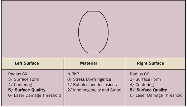
Figure 1. Example of ISO 10110 Standard drawing format with explanations of what goes where.
In contrast, the U.S. has failed to embrace this ISO standard, and there are some understandable reasons why. As a rule, the ISO optical standard format leaves a lot to be desired (Figure 1). In some ways, the standard is outdated; i.e., surface figure is still specified relative to a test plate. (Most modern interferometers have software to deal with this, but the ISO method for specifying surface form is based on outdated ideas. In addition to not saving time, old test plates can sometimes contain substantial surface form and radius errors. Those errors are not well accounted for by ISO 10110 and can easily propagate into manufactured parts. An easy work-around this issue is to add a radius tolerance to the Radius of Curvature callout in the drawing. This is generally recommended because radius errors are critical. Customers should not assume that a supplier’s test plates are good.)
Other issues include formatting that is restrictive, and prism and cube beamsplitter specifications that are rather awkward. This often deters designing engineers. Also, the surface quality callouts can become very complex. This deters suppliers. Another issue with ISO 10110 is that its surface inspection, much like the dimensioned Scratch/Dig standards, requires the use of a microscope to do it properly. Dedicated software that can quickly calculate the size and dimensions of surface defects then becomes necessary; a fully integrated and dedicated system can be an outstanding tool, but such systems can also be very expensive. Many U.S. shops, due to low demand for the standard, have yet to invest in these types of inspection systems. Without them, inspection per the ISO can be incredibly slow and a major cost driver.

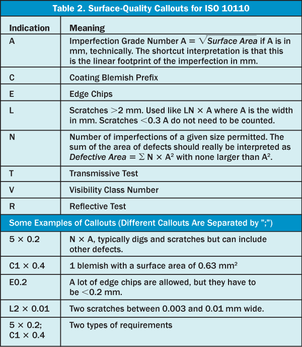
The section of the standard that deals with surface quality is ISO 10110-7 (called out on the drawing using “5/”). Figure 1 includes an example of the basic elements of an ISO drawing, and Table 2 has a list of the surface quality indications and how to use them.
ISO also has the advantage of giving designers more quantitative control over tolerancing. With experience, enough time and the right software, this analysis can be done in-depth. A computerized system capable of identifying and summing the area of various defects can be a significant time saver. Even with the advantages that ISO offers, using it with the wrong supplier can potentially reduce quality because, without the right equipment, the inspection sampling may need to be reduced to accommodate the increased amount of time needed to check individual optics.
Blemishes, stains, and spatter
These issues are not as well covered, and each standard deals with them in its own way. None of the solutions are particularly effective, nor are they based on how the defect will affect performance. Experience is usually the best guide for a designer, but as a good rule of thumb, apparent contrast is what matters for imaging, and size is what matters for laser systems. Lasers tend to be more impacted by diffraction, the scattering of high-intensity light and damage threshold. With imaging, the disruption of the final image is more important. Engineers and suppliers need to use their best judgment when dealing with these issues. Engineers should take the time to call out any requirements on their drawing explicitly, and suppliers should always at least make a phone call before sending parts with these defects, because what has no effect on one system may cripple another.

Takeaways
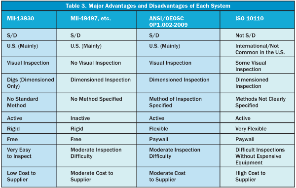
There are several ways to inspect surface quality, and each way has its own merits. The most important takeaway for suppliers, designers, and purchasers is to understand what using each standard will ultimately mean for the end product and end user. Using the wrong standard with the wrong supplier can negatively impact delivery without having any impact on part quality. Table 3 has a quick reference guide for each standard’s strengths and weaknesses to help make the decision of which standard to use.
References
1. R.K. Kimmel and R.E. Parks, ISO 10110 Optics and Optical Instruments-Preparation of drawings for optical elements and systems: A User’s Guide, 2nd. Optical Society of America, (Washington, DC, 2002).
2. Mil-PRF-13830B, U.S. Department of Defense (1963).
3. Mil-C-48497, U.S. Department of Defense (1974).
4. Mil-F-48616, U.S. Department of Defense (1977).
5. Mil-O-13830, U.S. Department of Defense (1954).
6. J. Salrin and G. Gutlwin, Surface Quality Standards for Scratch and Dig, J, K, and R. U.S. Army (Picatinny Arsenal, NJ, 1945).
7. ANSI/OEOSC OP1.002-2009, American National Standards Institute (2009).
8. ISO 10110:2010, International Standards Organization (2010).