As these switches become increasingly popular, it is important to understand how they work and where the technology is headed.
Michael Nagy, Olympus Microsystems America, and Sorin Tibuleac, ADVA Optical Networking
Dense wavelength division multiplexing (DWDM) systems have become the standard technology in high-capacity telecommunications networks ranging in distance from a few kilometers to thousands of kilometers. They combine multiple wavelengths on a single optical fiber, with each wavelength having data modulation rates up to 10 Gb/s. The newest technology pushes the rate up to 40 Gb/s. Each wavelength can carry any communications protocol containing Internet data, video or telephony information.
At the beginning and end of an optical link are “on” and “off” ramps, where information is converted from electrical to optical signals (at the on ramp) or vice versa (at the off ramp). Devices called “optical add/drop multiplexers” perform the functions of the on and off ramps by allowing some wavelengths to pass through toward other network nodes and others to be terminated at the local node.
The first generation of optical add/drop multiplexers were simply spectral demultiplexing and multiplexing filters (Figure 1) with fiber patch cords connecting each wavelength port on the demultiplexer to the same wavelength port on the multiplexer (for pass-through) or to local termination (for drop). Other patch cords brought locally generated signals to the vacated channels of the multiplexer (for add).
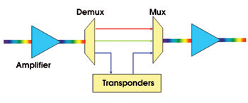
Figure 1. Shown is an optical add/drop multiplexer with demultiplexing and multiplexing filters for static add/drop or pass-through of DWDM wavelengths. Each infrared wavelength is represented by an arrow of a different color between the demultiplexer and multiplexer. In practice, the arrows are fiber optic patch cords, which must physically be moved from one connection to another to change which wavelengths are dropped and passed through by the optical add/drop multiplexer.
Even today, most networks still rely on costly and error-prone manual-patch-cord reconfiguration as the primary method of switching. For a network to adapt to changing traffic demands in various geographical locations, technicians must physically move the patch cords from one position to another. Recently, however, the emergence of reconfigurable optical add/drop multiplexers has enabled modernization of this procedure.
The most flexible type of reconfigurable optical add/drop multiplexer employs a 1 × N wavelength selective switch and a passive coupler, as illustrated in Figure 2 (N = 5 in this example). Multiple wavelengths received from the upstream network node are amplified and directed to the input port of the wavelength selective switch. The switch can select up to four of the wavelengths and pass each one to any of the four drop ports. Wavelengths not dropped are passed to the through port. Wavelengths are added either with an identical wavelength selective switch employed in reverse or with a simple passive N:1 fiber coupler, as shown in Figure 2.
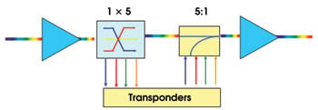
Figure 2. To eliminate the patch cords, a reconfigurable optical add/drop multiplexer switches any incoming wavelength to any exit port.
As DWDM technology matures and network loads multiply, the problem must be addressed: At a network junction with many incoming and outgoing fibers, each carrying multiple wavelengths, how can any wavelength on any incoming fiber be switched to any outgoing fiber?
In a simplified version of the answer, two incoming fibers each carry two wavelengths (Figure 3). The light from each fiber is initially split into two parts and sent to one of two 2 × 1 wavelength selective switches. At a switch, each wavelength is either blocked (lost) or placed on the outgoing fiber. Thus, any incoming wavelengths on either fiber can be switched to either of the outgoing fibers.
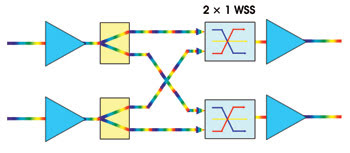
Figure 3. This example shows two incoming fibers, each carrying two wavelengths. The wavelength selective switches (WSS) make it possible for either of the wavelengths on either incoming fiber to be connected to either output fiber. The concept is scalable to N input and output fibers, each carrying many wavelength channels; in which case any incoming wavelength on any fiber can be connected to any output fiber.
Of course, if an incoming wavelength on one fiber is the same as an incoming wavelength on the other fiber, the two cannot be combined on an outgoing fiber. Moreover, the switching is accomplished at the cost of 50 percent of the incoming power. Nonetheless, with these restrictions in mind, the concept of Figure 3 can be extended to N incoming and outgoing fibers, each carrying an arbitrary number of wavelengths. The power loss — by a factor of N — is compensated by the amplifiers on either side of the switch.
Various designs
There are several approaches to the wavelength selective switch design that are based on technologies such as microelectromechanical systems (MEMS) micromirrors and liquid-crystal switches. Figure 4 shows a 1 × 5 wavelength selective switch with a MEMS-micromirror architecture. The DWDM wavelengths enter the switch from the left on a single-mode fiber that attaches to a fiber concentrator array. This optical component serves as the interface between the fiber and free space, with light entering via fibers and exiting as beams projected into space. (The interior of a hermetically sealed wavelength selective switch may be a vacuum or may be filled with air or an inert gas).
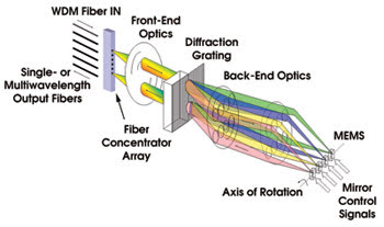
Figure 4. This 1 × 5 wavelength selective switch can connect any of the four wavelengths on the input fiber to any of the five output fibers (although for simplicity, it is shown connecting all of them to the same output fiber). Because this is a purely optical device, it also could function as a 5 × 1 wavelength selective switch if all the arrows were reversed.
Emerging from the concentrator array, each beam passes through several front-end optics components to magnify, collimate, refract or otherwise condition the beams so that they will impinge upon the dispersive element at the desired angle and magnification. A dispersive element, shown in Figure 4 as a transmissive diffraction grating, demultiplexes each beam into its constituent wavelengths. The individual-wavelength beams leave the grating and enter the back-end optics, which, as with the front-end optics, condition and manipulate the projected beams, sending each to a dedicated MEMS micromirror.
The switching engine of the wavelength selective switch comprises an array of MEMS micromirrors (see Figure 4, where only one row of micromirrors is shown for simplicity, and Figure 5, which is a photograph of an array of MEMS micromirrors). Generally, the mirrors are fabricated lithographically in silicon using bonding, coating and etching techniques developed in the semiconductor industry. Each mirror can be tilted independent of the others, on the axis of rotation shown in Figure 4. As it tilts, its beam reflects into the back-end optics, which condition it to impinge on the grating again. The grating multiplexes all incoming beams and sends them through the front-end optics to the output.
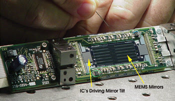
Figure 5. This 12 × 40 microelectromechanical systems (MEMS) array has integrated drive electronics.
Also in Figure 4, four MEMS micromirrors are shown. In a real device, there might be multiple micromirrors in each row, corresponding to the number of DWDM wavelengths supported by the device. Although the figure shows all beams coupled from the input fiber to the lowest of the five output fibers, each mirror can be tilted independently to “connect” its single-wavelength beam from the input fiber to any of the five output fibers. To “block” a wavelength, the micromirror simply tilts to an angle that steers its beam away from the output port.
The micromirror also can attenuate its wavelength by off-pointing slightly, intentionally causing slight decoupling of the light beam into the concentrator array. This can be useful in balancing the power in different wavelength channels so that a strong channel does not deleteriously affect other channels by, for example, saturating the gain in an amplifier. Attenuation precision of better than 0.1 dB is commonly specified in state-of-the-art wavelength-selective-switch products and is adequate for power equalization in all network applications.
All of the optical components in the light path must be optimized during manufacture for low insertion loss, proper geometric tolerances, freedom from surface defects, flatness, transmissivity/reflectivity, and low polarization dependence. As the active element, the micromirror criteria include flatness, reflectivity, sensitivity, drive voltage, full-scale tilt angle, pull-in angle, linearity, uniformity, drift over time and over-all reliability. Components must be rated for typical end-use lifetimes of 10 to 12 years and must maintain their specifications across all telecom environments: –5 to 60 °C temperature, high vibration and mechanical shock. The entire package must fit into a relatively small volume, typically a few tens of cubic inches (Figure 5).
Specifying wavelength-selective-switch components is complicated by the need to keep costs low and system reliability high. Designers must employ standard off-the-shelf components wherever possible and minimize total component count. This is especially important because wavelength-selective-switch annual volumes typically run in the low thousands, meaning that the cost/reliability benefits typically associated with high-volume components are generally not available. A substantial amount of a wavelength-selective-switch producer’s total cost is associated with vendor management, maintenance of second sources of supply and incoming component quality inspection.
Once high-quality, low-cost components are designed and procured, the wavelength-selective-switch assembly process takes place. Assembly requires high precision placement of components for free-space beam steering. Depending on the design, this can require placement tolerances of several tens of microns or tighter. Thermal mismatch of mating components, bond performance over time and temperature, and tolerance stack-up must be considered. Because of the relatively modest production volumes of these devices, full automation is not always the most cost-effective solution. Semiautomated processes, which allow assembly by unskilled or semiskilled workers, are often optimal. Custom jigs, fixtures, and in-line test hardware and software must be designed to support these processes while also collecting statistical data for process control.
Back-end testing of a wavelength selective switch represents a significant portion of the total effort. In this device, the number of possible routes equals the product of three parameters: number of input fibers, of output fibers and of DWDM wavelengths. Thus, our “simple” 5 × 1, 40-wavelength example requires multiple performance parameters to be measured on 200 routes. For a 10 × 10, 80-wavelength switch, we must test 8000 routes. Clearly, fully automated back-end testing is required, even for small-volume runs. Wavelength-selective-switch providers must work with their customers to agree on a thorough yet cost-effective test plan.
Research and development
The increasing popularity of wavelength selective switches in the optical telecommunications market is fueling research and development in several directions. The performance of existing N × 1 wavelength selective switches with 40 channels and up to nine input ports is continuously evolving toward lower loss and crosstalk, wider passbands and reduced polarization dependence. These performance improvements will enable wavelengths with data modulation rates of 40 Gb/s to experience minimum penalties when propagating through multiple wavelength selective switches.
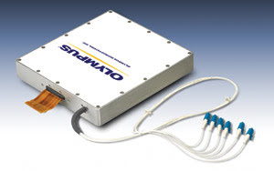
Figure 6. This is an example of a 5 × 1 wavelength selective switch.
Other developments include the increased number of wavelengths to 80 (at 50-GHz spacing) and the increased number of input ports. The higher number of wavelengths would meet the typical capacity requirements of long-distance transmission networks. The higher port count would increase the number of wavelengths that can be dropped at a network node with total reconfigurability (any wavelength on any port) when used in the 1 × N connectivity shown in Figure 2.
Improvements in MEMS manufacturing yield also would enable an N × N wavelength selective switch on a single module with performance, cost and reliability levels meeting the standards for commercial DWDM networks. The switches could have the functionality of an array of N, N:1 splitters and 1 × N wavelength-selective-switch units and lower transmission loss, and could occupy a significantly lower volume and require fewer fiber connections.
With these developments, wavelength selective switches will expand their current application space and will continue to affect the architecture of new telecom networks, playing a pivotal role in the quest for a more efficient, automated and reliable network.
Meet the authors
Michael Nagy is director of engineering at Olympus Microsystems America of San Jose, Calif.; e-mail: [email protected].
Sorin Tibuleac is director of optical systems at ADVA Optical Networking in Mahwah, N.J.; e-mail: [email protected].