Photonics Handbookpositioning
Vibration Control: Limiting Mechanical Noise
Vibration control plays a critical role in research and industry. Mechanical noise, for example, can obscure high-resolution images and affect the quality of nanotechnology processes. Fortunately, vibration can be controlled through proper experimentation, process design, and the use of specialized equipment.
MKS/Newport
In general, there are three common approaches to reducing mechanical excitation of photonic systems. The first is identifying the sources of vibration and implementing ways to eliminate or reduce their levels. The second is directly isolating the system from local ambient noise — isolation via distance from the disturbance or by using isolation products. The third approach is maximizing the rigidity and damping characteristics of any optical support structures. Work surfaces and optomechanical assemblies must be designed to reduce their response to any vibration transmitted through the isolation system.
Identifying vibration sources
Many potential sources of vibration within facilities can impact the results of precision processes or data collection. On one end of the spectrum are seismic events such as earthquakes, which impart both impulse and cyclic disturbances of potentially dangerous magnitude. In most seismic events, safety takes priority over performance, and having equipment that is properly protected and restrained is essential. Facilities along coastal areas can also be affected by tidal disturbances, depending on the magnitude of the waves and the sensitivity of the application. Another common ground-borne disturbance is vehicle traffic near buildings. Each of these could potentially excite additional resonances within structures or equipment that would lead to vibration or acoustic noise.
More typical sources of facility vibrations are those that originate within the building itself and are either transmitted along the floor or move entire labs. The most common of these is mechanical equipment such as elevators, pumps, AC units, motors, compressors, and similar rotating equipment. Common machinery problems include pump cavitation, unbalanced fans, and flow excitation of air-handling systems. Machinery faults can be eliminated through redesign or maintenance. Machines also should be installed on soft mounts that attenuate vibration before it is transmitted to the floor. In some cases, machinery can be contained in acoustic housings to filter airborne noise as well.
Even foot traffic from nearby hallways can impact sensitive experiments, depending on the building construction and level of traffic. Figure 1 illustrates many common sources of facility noise and their typical frequency ranges. In most traditional laser applications, building sway has no impact on stability or results, but in some emerging applications in bioimaging, such as live-cell imaging, building sway can affect the ability to clearly image cells suspended in fluid. Building sway can also impact scanning-probe microscopy applications, as many probe tips are sensitive to low-frequency vibration.
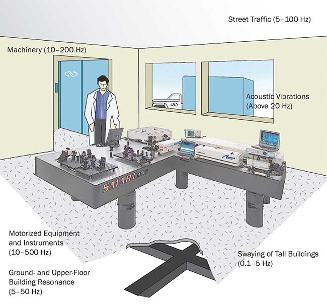
Figure 1. Mechanical noise comes from a variety of sources.
Some additional sources of vibration, which are often overlooked by even the most veteran scientists and engineers, originate within the experiment themselves or from inconspicuous sources. In laboratory environments, air ducts, doorways, and machinery all can introduce acoustic noise that could impact beam stability, especially in free-space applications.
The final sources of vibration to consider are those instruments, components, and accessories that may impart vibrations directly on the table surface or in very close proximity to the application. These are typically cooling fans, motorized positioners or other types of structures that are actively moving or are easily excited by external forces. Typical examples of these include large optical posts used to steer beam paths up or down, vertical breadboard structures or improperly fixtured components.
A critical first step toward building any high-stability, high-precision system is understanding the sources of vibration.
Isolating the system
After determining the potential sources of vibration in the environment, the next step is to find a way to minimize their effects. The best method is to avoid them altogether by selecting the optimal location within a campus, building, or room (just as in real estate, think, “Location, location, location”).
Being on lower-level floors helps eliminate building sway — accordingly, basement areas away from elevators, machinery, roads, or subways are optimal. This is where you would typically find sensitive scanning-probe microscopy labs, SEM/TEM labs or atomic physics experiments, since all of these involve large pieces of equipment that could be excited by low-frequency vibrations. Contrast this to some of the worst locations for sensitive experiments, such as upper floors next to mechanical rooms, elevators, roads, hallways, or foot bridges. Certainly some experiments are relatively immune to vibration disturbances and could be located almost anywhere, but matching the application requirements to the optimal location is the most effective and economical first step in constructing stable laser-based experiments.
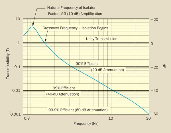
Figure 2a. Isolator transmissibility curve.
After the optimal location is selected, the next step is to determine which type of vibration-control equipment is required to meet the needs of the application. Any vibration-control system has essentially two goals: to effectively reduce the impact of environmental noise to a level that will maintain an acceptable relative spatial position of the elements within your system, and to prevent external sources from exciting resonances within system components.
There are typically two methods used for controlling system vibrations: isolation and damping. Understanding both of these and how they improve your system performance is critical to selecting the proper equipment.
Isolation systems are used to prevent floor disturbances from reaching the system platform. They are the first line of defense against vibrations in the lab and typically account for approximately 70% of a vibration-control system’s performance. The most common method of isolation is pneumatic due to its high performance, low cost, and ease of use.
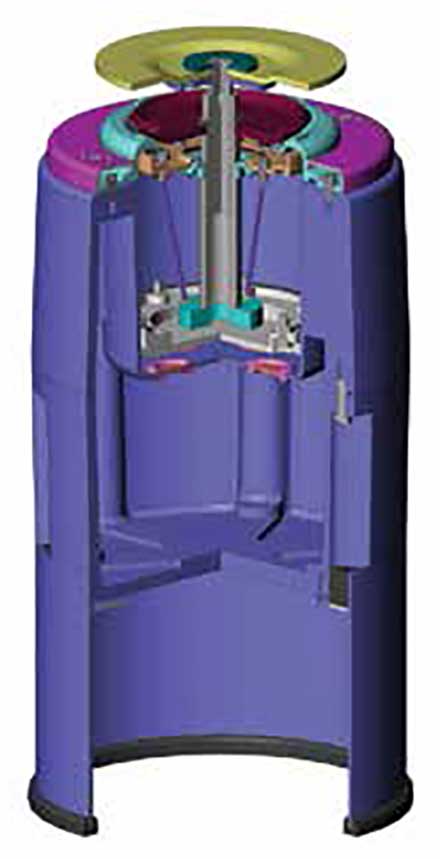
Figure 2b. Pneumatic isolator.
Systems typically consist of a reinforced rubber diaphragm and one or two pressure chambers joined by a flow-restricting orifice that acts to damp the air flow between chambers to improve the settling time of the table after disturbance. High-performance models offer horizontal isolation via a pendulum design, which can be very important for labs in upper floors of buildings. The constant height is maintained and controlled by an air regulator valve actuated by table motion. This system also provides self-leveling of the table when loads are moved across the work surface.
A quality pneumatic isolator would have a natural frequency of approximately 1 Hz and remove 99% of all vibration energy after 10 Hz. The typical figure of merit in isolation systems is a transmissibility curve that indicates the isolator’s response over a frequency range of 0.8 to 30 Hz. For most laser applications, quality pneumatic isolators provide sufficient reduction of floor disturbances.
The curve shown in Figure 2a is of a pneumatic isolator (Figure 2b), which has a 2000-lb load capacity, a 1-Hz vertical and 1.5-Hz horizontal natural frequency. This type of isolator is common among laser physicists due to its performance and load capacity, especially for larger multisegment table systems. For commercial applications, more engineers and scientists are opting for frame-type systems (Figure 3), which provide easier mobility and integrated accessories for optimizing inspection or assembly processes. These types of self-leveling pneumatic isolators provide the best price/performance of any isolation product.
Surprisingly, the second most common table support is a rigid-leg system. These are routinely used in applications where table surfaces must remain as rigid and stationary as possible. Common applications include x-ray crystallography or x-ray diffraction where beamlines are fixed and time domains are so short that isolation is typically not needed. Of course, it also helps that most beamlines are constructed on heavily reinforced concrete foundations.
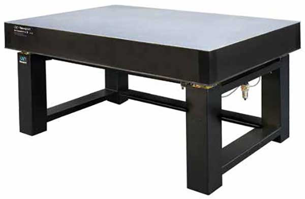
Figure 3. Integrated vibration control system.
Passive air mounts are also an economical choice but typically do not begin isolating until 10 Hz, which is a regime where automotive traffic, rotating machinery, and building resonances could move your table but not necessarily excite bending modes of the table. These air mounts also need to be refilled occasionally to maintain pressure since they are basically thick rubber balloons.
The final type of support system that receives mixed praise is active-isolation systems. These are typically based on a hybrid elastomer/piezo design where the elastomer or spring supports system loads and also provides isolation after a cutoff frequency of around 250 Hz. Their real benefit is their ability to provide low-frequency isolation required by some SPM, SEM, or TEM systems, or rapid isolation and settling of high-inertia motion events typical of wafer lithography tools. Because of their more complex design and control architecture, active-isolation systems typically cost 10× more than a comparable pneumatic system. Benchtop active-isolation systems are available at lower cost for isolating smaller instruments like benchtop AFMs and microscopes.
Maximizing rigidity and damping
After all sources of noise have been identified, reduced, or eliminated — and those remaining properly isolated — the next step in creating a stable system is to provide a sufficiently stiff and damped platform for the application. Selecting the right optical table can be confusing, especially if the system requirements and sources of noise are not fully quantified. Additionally, future performance levels that may be needed and potential changes in noise sources should also be considered. While effective vibration isolation is critical in reducing transmission of floor disturbances, of equal importance is effective vibration damping. The term “damping” is typically associated with optical platform structural damping that effectively dissipates the mechanical energy imparted on the structure and attenuates vibrations to acceptable levels. The industry term used to describe and quantify damping efficiency is dynamic compliance. Figure 4a is an example of a dynamic compliance plot.
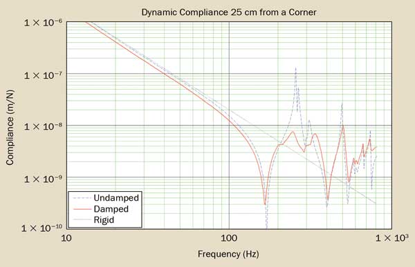
Figure 4a. Dynamic compliance curve of an optical table.
You can see that in the frequency domain from 10 to 100 Hz, the table exhibits rigid body behavior. This means that when the table experiences disturbances in this region, rather than deflecting, it moves as a solid body. In typical laser applications, this would not affect beam stability or excite component resonances. However, disturbances imparted on the table in the region from 100 to 1000 Hz could excite the resonance modes of the table or the optical components, as indicated by the sharp peaks, and induce flexural movement of the structure. The most common sources of excitement in this region are acoustic disturbances, rotating machinery, fans or motorized positioners. It is in this region where beam paths would be disturbed due to the micron-level deformations in the platform; optical component resonances would become excited, and certain beam instability would occur. This is also the region where structural damping techniques are used to reduce the magnitude of the resonance peaks, thereby minimizing disruptions to the table surface and, in turn, improving beam stability.
There are many different methods for reducing structural resonances; each has its benefits and limitations. The first is known as broadband damping. In this approach, the vibrating elements are damped by affixing a flexible material like rubber or an elastomer to the surface (noise reduction in car doors is one example). The broadband dampers can also be constructed by supporting nonstructural elements within the table with pieces of rubber or elastomer. In this design, the vibration energy in the table is partially absorbed by the “floating” mass. Another approach to structural damping is using tuned mass dampers, which take the concept of broadband dampers and add an additional element to improve performance. In a tuned mass damper design, as shown in Figure 4b, large nonstructural masses are supported by stiff springs that are tuned to the resonances of the structure. This damper is then rigidly fixed to the internal structure of the table. The energy of the moving mass and springs is then dissipated by a viscous material like heavy fluid or elastomers. With tuned mass dampers, the energy absorption is much more efficient than with broadband dampers, resulting in a more stable platform. Hundreds of research papers have been published on various methods of structural damping, and one conclusion they all have in common is that the most effective method of structural damping is through the use of tuned mass dampers.
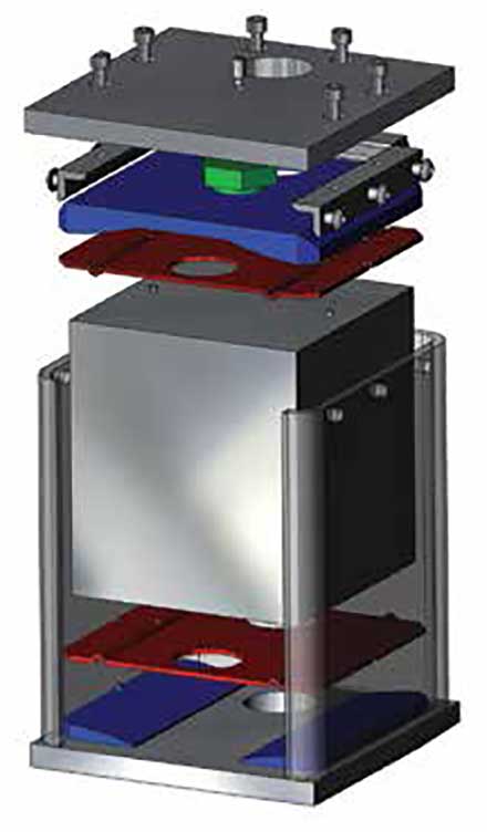
Figure 4b. Tuned mass damper.
The graph in Figure 4a also illustrates how effective a tuned mass damper approach is at reducing optical table resonances. You can see that the undamped table in this test exhibited a resonance at approximately 250 Hz. Tuned dampers then installed to effectively dissipate this energy reduced tabletop motion by 10 times. A 20-dB reduction in main resonance peaks is not uncommon for an effective tuned mass damper system.
The use of tuned mass dampers becomes even more important when considering applications that require multisection tables or very large tables, like the one shown in Figure 5. The larger size of multisection tables results in lower resonant frequencies, and the complex system shapes can also shift the dominance of mode shapes, which broadband dampers cannot effectively reduce. In these types of systems, the structural resonances can be measured, and appropriately tuned mass dampers can be installed to reduce the resonances. For very complex multisegment table systems, there is simply no better method of damping than tuned mass damping.
Most optical table suppliers differentiate their platforms based on the amount of structural damping that has been put into the table. Entry-level tables are built with a rigid, inherently damped honeycomb core but without additional damping methods. A table like this would be sufficient for most labs, such as for teaching basic optics or for fiber optics applications. In these applications, there tend to be few elements in the setup that generate vibration, plus the elements themselves are not sensitive to vibrations, since they are investigating feature sizes in the 50- to 100-µm range.
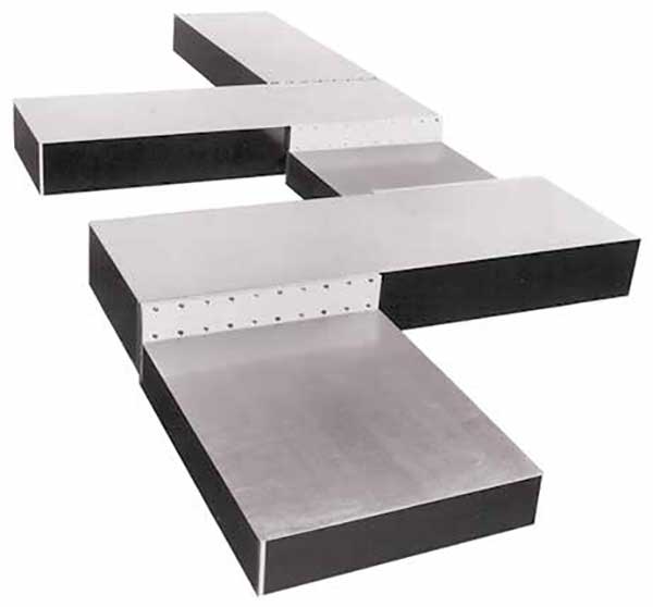
Figure 5. Complex multisegment table stem.
For more advanced applications like multiphoton microscopy, optical sensor development or assembly, and ultrafast studies, a table with nominal tuned mass dampers or maximum broadband damping is typically needed. In these types of applications, elements of the setup can be a source of vibration (fans, chillers, spinning disks), plus the applications are also looking at much smaller detail sizes in the 10- to 50-µm range. Having some method of damping is critical to reaching these performance levels in any operating environment.
For more sensitive applications such as holography, nanofabrication, or lithography where features' sizes are in the range of 0.1 to 10 µm, absolute platform stability is critical. Platforms that incorporate multiple tuned mass dampers or active damper systems are best suited to providing this performance. These types of products are able to reduce system resonances by more than 20 dB, which has been shown in testing to provide two times more reduction than the best broadband damped systems.
Upgradable platforms and solutions have been introduced that allow users to improve the performance of their table in the future, should they need it. The benefit with these systems is that they reduce the initial acquisition costs without jeopardizing future performance. In some of these products, the additional dampers are installed within pockets built into the table. More advanced solutions include active dampers and a controller that can be bolted to existing structures to help reduce structural resonance, like the example shown in Figure 6.

Figure 6. Isolation table with bolt-on dampers.
A combined approach
The creation of a mechanically stable experimental system may require a combination of the three approaches: reduction at the source, isolation from the source, and maximizing stiffness. Approaching the problem in the order presented can prove to be the most cost-effective and result in much better performance in the long term. A number of products are available that can help reduce environmental disturbances, and selecting the proper products and assuring their proper installation and maintenance will help provide a stable platform for your sensitive applications.
/Buyers_Guide/MKS_Newport/c10218