Commonly used to produce thin films during integrated circuit production, this low-pressure chemical vapor deposition technique can be used for optical thin films.
EVAN CRAVES, DEPOSITION SCIENCES INC.
Antireflection (AR) coatings are some of the most extensively employed types of optical thin films. By reducing the amount of light reflected from a surface, such coatings improve system throughput, increase contrast, and enhance signal-to-noise ratio in virtually every type of precision optical system and in commercial products such as eyeglasses, flat-panel displays, and architectural windows.
An optical thin film consists of one or more layers of coated material, with individual layer thicknesses typically ranging from a few nanometers to several microns. Producing a useful coating requires precise control of deposition so that the desired sequence, uniformity, material thicknesses, and indices of refraction are achieved. Good adhesion is also important if the optic is to be mechanically durable, as is the ability to retain consistent properties in the presence of temperature and humidity swings for applications requiring environmental stability. Economic factors, such as cost, also dictate the use of production equipment appropriate for large batch sizes and short cycle times.
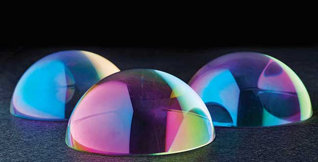
Uniformly coated glass hemispherical domes. Courtesy of Deposition Sciences Inc.
The two most commonly used deposition technologies for producing optical thin films that meet these criteria are evaporation and sputtering. There are numerous variations of both methods.
In a traditional evaporative coating chamber, one or more racks hold the substrate material to be coated. The first step in the process is to pump all of the air out of the chamber to achieve a very high vacuum (10−6 torr or better).
A succession of coating materials is then evaporated, typically using either resistive heating or electron beam bombardment. Because the chamber is in high vacuum, the mean free path of evaporated atoms or molecules is several meters. They stream out and condense onto any surface that has a direct line of sight to the source.
Consequently, the deposition rate is highly dependent upon the distance and relative angular orientation from the source to the substrate surface.
To maximize layer uniformity, the racks are rotated during coating such that every part experiences the same time-averaged distance from the source (Figure 1). Complex internal masking also is often used to enhance deposition uniformity throughout the chamber, and, since only one side of the component faces the material source, it is necessary to repeat this entire process when coating both the front and back surfaces of a single component.
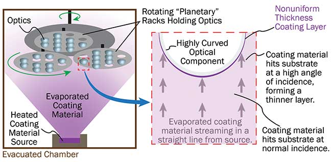
Figure 1. The line-of-sight nature of evaporative coating produces nonuniform film thicknesses on highly curved parts, such as steep aspheres and domes. Courtesy of Deposition Sciences Inc.
However, no matter what the specifics are of a particular evaporative coating implementation, the line-of-sight nature of deposition makes it difficult to produce films of uniform thickness on highly curved parts. This is due to the higher impact angle of coating material at the edge of the part compared to the center, resulting in different deposition rates and structure normal to the surface.
The various sputtering processes used for thin-film coatings typically employ a different mechanical configuration than evaporative methods. At Deposition Sciences Inc. (DSI), for instance, the parts to be coated are mounted on a rotating drum facing outward with the deposition targets arranged in a concentric circle that faces inward toward the drum. Similar to evaporation, sputtering is performed under relatively high vacuum conditions with a small amount of reactive gas present in the chamber. Therefore, sputtering has similar characteristics to evaporation in terms of depositing by line of sight, the types of nonuniformities when coating highly curved parts, and the need to duplicate runs to coat back surfaces.
Vapor deposition
For the majority of optics, these traditional coating methods are perfectly adequate. To meet the growing need for producing uniform thin films on highly curved optics, DSI has created a form of low-pressure chemical vapor deposition (LPCVD) called IsoDyn. This type of chemical vapor deposition is a well-established technology in the semiconductor processing field, where it is used to produce thin films during integrated circuit production, but it is not commonly used for the manufacture of optical thin films.
During the process, the coating material is created by the chemical reaction of a precursor gas at the substrate surface rather than being evaporated or sputtered from a material target. Specifically, parts to be coated are put into an evacuated chamber and heated to the necessary reaction temperature (approximately 500 °C). The chamber is then filled with a diluted chemical vapor at relatively high pressure (usually 0.1 to 5 torr). The precursor molecules diffuse to the substrate surface and chemically react, resulting in deposition of the desired thin film on all exposed surfaces. This process is repeated with various precursors to produce a multilayer coating (Figure 2).
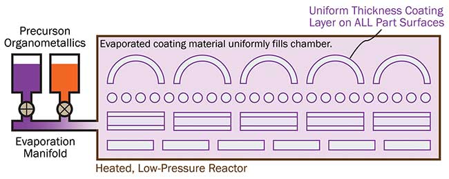
Figure 2. In the IsoDyn process, the evaporated coating material uniformly fills the reaction chamber, producing a uniform thickness coating on all part surfaces, regardless of shape. Courtesy of Deposition Sciences Inc.
Reaction is surface-driven, so deposition occurs on every surface within the chamber, regardless of its position or orientation, and does so with the same growth structure normal to each surface. This makes the technique useful for producing highly uniform coatings on parts with unusual shapes or extreme curvatures.
Because the deposition is isotropic, parts don’t need to move during coating, and any tooling effects on deposition are slight. In addition, the entire volume of the chamber can be filled with parts. This means higher throughput and lower production cost. Economy is further improved because all surfaces (front, back, and sides) of an optic are coated in a single run.
As the parts cool to ambient temperature after coating, the deposited molecules pack tightly as the substrate shrinks, resulting in films with greater density than are typically achieved with other deposition techniques.
The process gives rise to extraordinarily durable coatings because of the chemical bonding of material to the substrate surface during deposition. Furthermore, as the parts cool to ambient temperature after coating, the deposited molecules pack tightly as the substrate shrinks, resulting in films with greater density than are typically achieved through other deposition techniques.
The overall result is the production of coatings that can survive repeated handling and abrasion, and perform over a very wide ambient temperature and humidity range. This also results in coatings with excellent laser damage threshold characteristics.
Ball lenses
Ball, or full spherical lenses, are inexpensive and offer a mechanically compact optical means of collimating the output of an optical fiber or diode laser. They can also be used in pairs for fiber-to-fiber, diode-to-fiber, and fiber-to-detector coupling, particularly when access to the collimated beam between the two balls is required. They are widely used in telecommunications and medical applications.
Ball lenses are currently fabricated from a wide variety of materials with transmission in the visible, NIR, and SWIR, including N-BK7, fused silica, N-LaSF9, spinel, sapphire, N-LaSF35, S-LaH79, and cubic zirconia. Typical ball lens diameters range from 0.25 to 10 mm.
The high curvature of ball lenses makes it difficult to apply an antireflective coating by evaporative or sputtering methods. Additionally, their small size presents another problem: The tooling necessary to hold a ball lens in an evaporation or sputtering chamber inevitably leaves an uncoated band that runs around the entire circumference of the part. As a result, the user must then control the orientation of the ball lens during assembly so that this uncoated band is perpendicular to the optical axis to minimize its impact. This can be difficult and time-consuming to accomplish, increasing assembly costs (Figure 3).
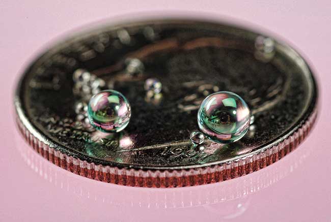
Figure 3. Uniformly coated ball lenses. Courtesy of Deposition Sciences Inc.
The AR coating process solves both of these problems simultaneously. Specifically, it yields a uniform coating over the entire sphere surface with negligible tooling effects. Single- or dual-band AR coatings with less than 0.25 percent reflection per surface can be readily produced using this method.
Rod lenses
Diode lasers are used in a very broad range of applications, including fast-developing lidar object-avoidance systems for autonomous vehicles. Unlike most other laser types, virtually all edge-emitting diode lasers produce an asymmetrical and astigmatic beam. As a result, it has been common practice to use some sort of anamorphic or cylindrical lens-based system to correct for this.
Rod or full cylinder lenses can be used for this task and are particularly attractive for several reasons. First, these components can be created by drawing a preform into a long fiber, just as fiber optic cables are fabricated. However, in this case, the preform is homogeneous (without a core and cladding having different indices of refraction). This is a far quicker and less costly method than traditional grinding and polishing, and also more readily yields components having a small diameter (<10 mm).
A rod of nearly any length can be produced in this manner and then subsequently cut into the desired finished length (Figure 4).
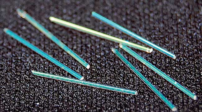
Figure 4. Uniformly coated rod lenses. Courtesy of Deposition Sciences Inc.
The challenges encountered in coating small-diameter rod lenses using sputtering and evaporation are similar to those experienced with ball lenses: difficulty in getting an isotropically uniform coating, the need for multiple runs to coat all sides of the fiber, and tooling marks that require careful part orientation during assembly.
The LPCVD coating process addresses all of these issues. Furthermore, it’s quite feasible to coat the rod lenses in long lengths and then cut them to final size afterward. This simplifies and speeds processing, which in turn reduces cost.
Domes
Domes have been used in missile and reconnaissance/surveillance applications by the military for many decades. These are often ellipsoidal or ogival optics, some of which can have a very large aspect ratio (much longer than they are round). The domes are placed over a vision or targeting system, which sits on either the tip of a missile or somewhere on the skin of an aircraft. Optically, they act as a window, adding little or no optical power to the vision system, but mechanically they provide the curved shape necessary to maintain the proper aerodynamic performance of the structure.
Domes are commonly fabricated from a wide range of visible and IR transmitting materials, including silicon, germanium, zinc sulfide, zinc selenide, sapphire, spinel, and various glasses. Virtually all domes are AR-coated on both their inner and/or outer surfaces.
Two key requirements for dome coatings are uniformity and mechanical durability. Traditional coating methods produce a thinner coating on the steeper part edge, one that is naturally more porous, leading directly to reduced mechanical durability. In contrast, the LPCVD coating technology delivers both highly uniform and mechanically durable coatings because of its high and uniform material density.
Lasers and vision systems continue to push into an ever-wider range of applications, including high-volume consumer uses.
For the latter, designers may sometimes use nontraditional components, often having unusual shapes and functionality, to meet the relentless drive to reduce cost and improve performance. This, in turn, challenges fabrication and coating methodologies to keep pace. The LPCVD coating has emerged as one tool for meeting these demands, particularly for highly curved optics, optics with complex 3D shapes, and micro-optics.
Meet the author
Evan Craves is a chemical engineer at Deposition Sciences Inc. where he manages LPCVD coating projects. He has over 19 years of experience in optical thin films and received a bachelor’s degree in chemical engineering from the University of California, Davis.