Photonic power’s insensitivity to various environmental conditions suggests such benefits as safety and efficiency.
Dr. Jan-Gustav Werthen and Mort Cohen, JDSU
Traditionally, copper and coaxial cable have been used to power remote electronics such as sensors, transducers and communication devices. However, these devices frequently are located in environments that are hazardous, electrically noisy, inaccessible or exposed to extreme weather. These conditions make copper and coaxial cable subject to electromagnetic interference, radio frequency (RF) heating, ground loops and lightning damage.
A new form of power delivery, photonic power, escapes these problems by delivering optical energy through optical fiber to drive remote electronics. Fiber optic cable is immune to electrical current, RF and magnetic fields, and lightning discharge.
High conversion efficiency
Recent advances in fabrication techniques and materials have resulted in increases in optical-to-electrical conversion efficiencies to levels that exceed 50 percent (see “Photovoltaic Power Conversion Using Monochromatic Light,” page 70). This makes it feasible to use photonic power for an array of applications.
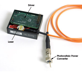
Figure 1. The photonic power module — including a laser diode, laser driver, photonic power converter and fiber interconnect — constitute a compact, readily installed package.
In a photonic power module, up to 5 W of optical power is launched into multimode or single-mode fiber (Figure 1). This power illuminates a photovoltaic power converter — typically a 2 × 2-mm GaAs or InP chip composed of several PN junctions that are connected in series such that the voltages from the junctions are additive — that is collocated with the remote electronics up to several kilometers from the laser source. The delivered optical power is converted to electrical power with 50 percent efficiency to drive the remote electronics.
Photonic power provides a safer and more environmentally friendly power delivery system than copper and coaxial cable and also is interference-free. Delivering power over fiber offers several advantages:
• Enhanced signal and data integrity resulting from the use of isolated power, which is immune from noise, from electromagnetic interference and from the effects of high voltage and of RF and magnetic fields. Networks employing transceivers, amplifiers, sensors and actuators that operate in these harsh environments can transmit interference-free data because of the electrical isolation afforded by an all-fiber network.
• Lightning-proof and spark-free performance based on the nonconductive nature of fiber. This feature is critical in many industries that are subjected to severe outdoor conditions, such as cellular base stations and electrical power grids, or in applications that must avoid the potential for spark-ignited explosions, such as the monitoring of fuel gauges and cabin door interlocks in aircraft.
• Increased human safety based on the elimination of cable heating, which is prevalent in copper-based systems. This is of particular benefit in applications such as magnetic resonance imaging, in which heating can create a serious risk of burns if the cabling comes in contact with the patient.
• Faster installation and reduced maintenance as a result of the lightweight nature of fiber. Fiber can be installed more quickly and more cost-effectively than coaxial cable. These features are important in wireless communication deployments such as cellular base stations and metropolitanwide WiFi networks because photonic power speeds installation, permits the more optimal placement of RF subsystems and lowers the cost of ownership by reducing the damage caused by lightning strikes and severe weather conditions.
• An environmentally friendly and safer method of current sensing in high-voltage electric power transmission and distribution grids. The traditional method of measuring current in very high voltage networks is to reduce the voltage. An alternative method is to locate the electronics in the high-voltage field and to power the electronics over fiber. The use of fiber optic cables isolates the current transducer or sensor from ground potential. This configuration offers several benefits, including the avoidance of the possible leakage of harmful transformer materials into the environment, the reduction of both the overall weight and the costs associated with transformer installation, and the elimination of the possibility of explosion.
Medicine
Magnetic resonance imaging technology can display images of the human body by detecting nuclear magnetic resonance signals. These signals are detected by RF coils that amplify the signal to sufficient levels for reading by the processing electronics.
Typically, a stiff, bulky, shielded copper cable provides power to the coil amplifier. In the presence of the high switching fields used in the imaging process, common mode signals and ground loops present a challenge to signal integrity and can cause cable heating that may result in patient burns.
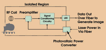
Figure 2. Photonic power is converted to electrical power in the photovoltaic power converter, and the electrical power drives both the preamplifier and the signal-processing circuitry. Magnetic resonance imaging data, picked up by the radio-frequency coil, is returned on a second fiber to the base unit, where it generates an image.
The use of nonconductive fiber eliminates these risks and offers the promise of an improved signal-to-noise ratio (Figure 2). Because fiber requires a smaller cross-sectional area, more coils can be powered in the same available volume, offering improved image quality (Figure 3).

Figure 3. A magnetic resonance image created using photonic power is clearer than a conventional image because more space is available for the RF coils.
Energy
Photonic power can be used to power current transducers for current monitoring or protection in very high voltage environments. In a typical installation for an electric power application, measurement is accomplished by converting the analog output from a current transducer to digital format (Figure 4). The use of fiber optic cables isolates the current transducer or sensor from ground potential.
This configuration is lighter and environmentally safer, and offers significant cost and space savings over conventional oil or SF6 gas-filled high-voltage instrument transformers. Potentially explosive transformers are replaced by an electrically isolated, spark-free optical installation.
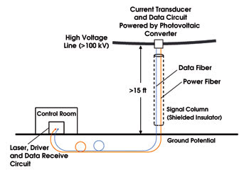
Figure 4. Power to drive the instrumentation on the high-voltage line is delivered over one optical fiber, and the instrumentation’s signal returns over the other. No electrical conductors are in proximity to the high voltage.
Wireless communications
Many applications utilizing remote RF antennas, including global positioning system (GPS) timing networks, digital broadcast TV, mobile cellular networks, indoor distributed antenna systems, and WiFi and WiMAX networks, rely on local antennas that can be situated in electrically noisy locations. They can be fully supported with dielectric optical fiber for both signal and energy. Analog and digital signals are commonly routed to and from these antennas through standard optical fiber. Optical energy for preamplifiers or low-power transceivers also can be efficiently delivered through noise-immune and nonconductive optical fiber.
In wireless communications applications, GPS receivers provide timing signals for the synchronization of voice and data streams (Figure 5). In some cases, they also provide stability inputs to a local frequency source. Many recent installations mount the GPS engine so that the antenna/amplifier assembly is in clear view of the GPS satellite.
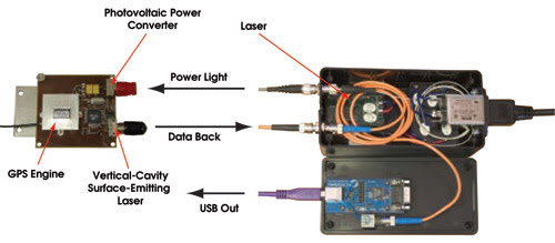
Figure 5. A GPS engine is powered by photonic power. As in the other examples, both the power into the remote package and the data returned are carried over optical fiber, electrically isolating the remote package.
The use of photonic power eliminates the need for coaxial connections, line amplifiers and lightning suppression. The coaxial/power connection is replaced by an all-fiber solution. The laser diode source, mounted in the indoor equipment bay, provides light transmission over the fiber over distances in excess of 500 m.
The converter changes the light to electrical power to drive the outdoor amplifier and GPS engine, and the GPS engine converts the RF signal to digital format. A vertical-cavity surface-emitting laser optically modulates the data stream and launches the optical signal onto the fiber for transmission to the equipment bay for processing.
Meet the authors
Jan-Gustav Werthen is director of engineering (e-mail: [email protected]) and Mort Cohen is the product line manager (e-mail: [email protected]) for JDSU’s Photonic Power Business Unit in San Jose, Calif.
Photovoltaic Power Conversion Using Monochromatic Light
The photovoltaic power converter is a miniaturized semiconductor diode array that converts optical power to electrical power. When light emanating from an optical fiber illuminates the photovoltaic power converter, three parameters determine the overall conversion efficiency.
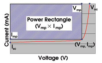
In a curve of the current vs. voltage of a typical photovoltaic power converter under illumination, the fill factor is shown graphically as the ratio of the area in the power rectangle (blue shading) to that enclosed by the red curve.
First, there is absorption of the photons, typically of monochromatic light and with the wavelength chosen for optimal conversion efficiency. This absorption results in a photocurrent, not unlike the current generated in a photodiode. A photodiode, however, must be fast-switching and often is reverse-biased — therefore, drawing, not delivering, power. The photovoltaic device operates mostly in DC, or continuous mode, and is optimized to deliver power.
Second, the photovoltaic power converter must operate at a sustained, steady voltage that is useful and capable of driving electronic circuitry — usually between 3 and 5 V for most applications.
Third, the photovoltaic power converter must deliver the current and the voltage at the same time to deliver power. The figure of merit describing its ability to do both is called the fill factor, or ff. It is defined empirically as
ff = (Imp × Vmp)/(Isc × Voc)
where Imp is the current at the maximum power point, Vmp is the voltage at the maximum power point, Isc is the short-circuit current and Voc is the open-circuit voltage.
A photovoltaic power converter operating close to Isc will deliver considerable current but little or no voltage and, hence, no power. Likewise, a converter operating close to Voc will have considerable voltage but almost no current, and again will deliver no power.
Combining the three parameters results in the conversion efficiency, which equals (Isc × Voc × ff)/Pin, where Pin is the input light power. Recent advances have made it possible to optimize these parameters in the same device and to produce a conversion efficiency of more than 50 percent, which compares extremely well with the theoretical optimum efficiency at room temperature of approximately 63 percent.
This stems from the fact that the photon-to-electron conversion is 100 percent, ignoring even the smallest reflection loss. The voltage, again at room temperature, is 70 percent of its theoretical limit, which can be obtained only close to 0 K. Finally, the fill factor, or “squareness” of the power rectangle, is at 90 percent. (Because the photovoltaic power converter is a diode and follows an exponential behavior, the squareness can never reach 100 percent.)
To date, the highest efficiency measured on a photovoltaic power converter is 55 percent, or within 87 percent of the theoretical limit at room temperature.