Lidar and radar offer distinct, though complementary, capabilities. An integrated approach is maximizing the benefits of both modalities in a single package.
TOMMASO CASSESE AND ION VORNICU, SILICON AUSTRIA LABS
For decades, end users and systems designers have valued radar technology for its reliability. Especially in adverse weather conditions in which sensors based on other modalities are apt to fail, radar is a dependable technique offering broad application potential.
As a result of this robustness and widespread applicability, radar today is established as a standard sensing system in several high-growth technology sectors. The automotive industry, for example, has been a key driver of radar sensor miniaturization and overall performance improvements. The commercialization of radar for passenger vehicles predates the turn of the century, and radar sensors are also now commonly deployed in advanced driver-assistance systems, including for adaptive cruise control, autonomous emergency braking, and blind-spot assist.
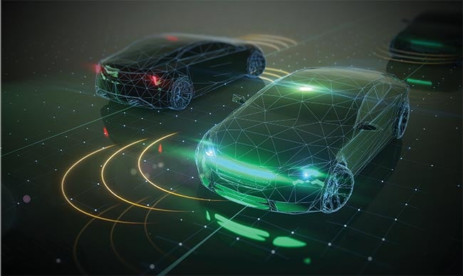
Courtesy of iStock.com/Just_Super.
However, increasingly complex urban driving scenarios are intensifying the demands on sensor technology. Situations involving turn-across-path or junction crossings with pedestrians and cyclists pose particular challenges, and scenarios such as these now verge on being included in crash test ratings. Sensors that are capable of tracking multiple, smaller, and more agile objects simultaneously are therefore required to make timely, accurate identifications in critical situations.
While the current class of standard commercially available radar sensors excels in detecting single large objects, such as cars, they struggle to distinguish between multiple objects that are close together.
High-resolution radar, often referred to as imaging radar, addresses this limitation. This technology uses multiple transmit (TX) and receive (RX) channels
to offer object separation that is comparable to that achieved via classical lidar. However, these systems require a much larger front-facing area due to the increased number of antennas. Furthermore, multiple-input multiple-output radar reduces the footprint of the antennas by implementing virtual channels with improved aperture.
Considering that acquiring better resolution requires more complex processing,
R&D projects are exploring the integration of radar with camera sensors. These efforts aim to further enhance radar’s capabilities at a time when manufacturers are progressing toward higher levels of vehicle automation.
Starting with Level 3 — Conditional Driving Automation, lidar sensors are now expected to play an increasingly important role in the next stages of growth in autonomous mobility. Lidar can serve as a safety backup and validation technology, offering capabilities that overlap with cameras, such as optical texture detection.
The high-resolution specialist
Lidars are complex systems, mainly built by components on the TX and RX sides. Typically, the TX side houses a laser along with its controller and a laser projection system, and the RX side consists of a light signal detector unit with signal readout and a data processing unit. Unlike camera imaging, lidar is independent of environmental brightness, due to its generation and use of a light source. By emitting laser pulses and measuring the time that it takes for them to return after hitting an object, lidar produces a detailed point cloud that accurately represents the surrounding environment. This is crucial for applications such as autonomous driving, in which understanding the exact
position and shape of objects is paramount for safe navigation.
Though the distance detection capabilities that lidar offers are comparable to that of radar, and although lidar excels in spatial accuracy, the technology presents
several drawbacks. One significant challenge is its performance in adverse weather conditions such as fog, rain, and dust. In such conditions, the combination of accurate velocity measurements and reliable object detection offered by radar is a crucial complement to the strengths of lidar.
The case for a sensor fusion
The integration of lidar and radar into a single module offers a powerful combination of capabilities that neither technology can provide alone. This fusion of high-resolution data from lidar with the all-weather performance of radar creates a comprehensive sensing system with several important advantages, especially for automotive applications. One specific example, urban traffic management, benefits from the accurate detection and classification of a diverse array of closely spaced objects — something that is essential for both safety and efficiency.
Radar can additionally be used to identify regions of interest within a frame, allowing lidar to then be deployed to focus its scanning on these areas. This targeted approach reduces the volume of point cloud data that is generated, thereby minimizing storage requirements and simplifying data processing and analysis. This efficiency is necessary in settings with limited computational resources, or for real-time data processing, such as in autonomous vehicles.
Additionally, the integration of radar’s detection capabilities with lidar’s scanning precision reduces the time required for data collection per frame. In applications such as search and rescue, for example, this efficiency is paramount. Quick and accurate scanning of a map of an affected area can be the determining factor of a successful search and rescue effort to locate survivors.
Lidar fundamentals
Different solutions have been proposed for lidar sensors, many of which are already on the market. The primary differentiator between lidar systems is the measurement principle; depending on the measurement mechanism, lidar systems are mainly based on time-of-flight (ToF) — either direct or indirect — or frequency-modulation continuous wave (FMCW) engines.
ToF sensors measure the time required
for a light pulse to travel from the transmitter to the object and back to the receiver. Direct ToF sensors typically
require higher power, short pulses, and fast electronics such as picosecond time-to-digital converters. This class of sensor currently dominates the lidar market.
Indirect ToF sensors are based on amplitude-modulated continuous wave (AMCW)-based sensing mechanisms; these systems emit a continuous signal, the power of which is amplitude-modulated. Demodulating the backscattered signal, these sensors calculate the distance to the object based on the phase shift of the received signal. The advantages in this case are that the receiver does not require very fast electronics, and it features a smaller pixel pitch, reaching a higher resolution than the direct ToF sensor. Nevertheless, the backscattered signal has quite low power when received by the sensor, impairing the depth accuracy, especially above the medium range.
FMCW lidar sensors deliver intrinsic amplification connected to the use of homodyne reception; for example, the received signal beats with the local oscillator, and both are generated by the same laser source. This process puts FMCW lidar into favor in cases of high losses due to absorption and/or long-range application. Broadly, this class of lidar sensors offers the potential to overcome ToF and AMCW limitations. Additionally, FMCW has an intrinsic immunity to sun radiation and other incoherent radiations.
From the imaging standpoint, the laser projection system found in lidar systems is based either on scanning or flash, or a combination of both mechanisms. Scanning systems are either implemented with conventional mechanical parts, microelectromechanical system (MEMS) devices, or solid-state solutions, such as programmable VCSEL arrays or optical phase arrays (OPAs).
In the most advanced mechanical scanning systems, the laser source is fixed, while a mirror is continuously rotating, featuring a wide horizontal field-of-view (FOV), typically 360°. The vertical FOV is typically smaller than the horizontal and it is implemented in a flash manner. The reduced FOV comes mostly from a practical point of view — automotive applications do not typically require >30°. However, the mechanical scanning is quite bulky, and it cannot be scaled cost-wise because ~70% of the lidar cost is due to the macromechanical system. A MEMS mirror solution could overcome this scalability bottleneck, though such a solution would be limited in horizontal resolution. And additional dimension considerations, such as eye safety and miniaturization, must be accounted for.
Silicon photonics: The fusion enabler
Given these performance advantages and drawbacks, an ideal lidar system will combine solid-state (for miniaturization)
and scanning (for eye safety) with flash
(multiple channels for increased frame rate). On top of this, it is known that the 1550-nm wavelength is more eye-friendly at the same optical power and emission conditions.
Additionally, an FMCW engine can operate with less optical power than a ToF engine due to the advantages of coherent detection. An additional benefit of using the 1550-nm option comes from the possibility to use (integrate) components developed for telecommunications applications into the lidar system. This can highly reduce the development time and improve yield.
Given the need for discrete components to enable this miniaturization, advancements in PICs are very promising for
the integration of FMCW lidar. Recent
developments in electro-photonic integrated circuits (EPIC) technologies specifically offer an ideal platform. The lidars can be truly miniaturized, because the electronic and photonic components can be monolithically integrated on the same chip.
A major leap in the EPIC FMCW lidar system concept beyond the monolithic integration potential is the replacement of the lenses; these components are the primary component-level limitation to the miniaturization of ToF-lidar systems. Various integrated photonics platforms have been proposed as suitable for integrating not only beam forming and steering devices, such as OPAs employing electro-optical or thermo-optical effect to control the beam direction, but also for integrating the full lidar system. This is possible because the multiple components needed for an FMCW lidar sensor have already been developed in integrated photonics platforms for telecommunications applications, and primarily at 1550 nm. These components can now be repurposed for the disruptive application of lidar without the need for further reconceptualization.
The future: Opportunities and challenges
A fully integrated radar-lidar sensor could greatly enhance the capabilities of autonomous vehicles, environmental monitoring, and other critical applications, providing reliable, high-quality data in the most challenging conditions (Figure 1).
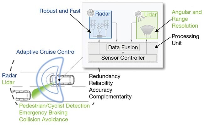
Figure 1. The radar-lidar sensor fusion concept shows the system in an automotive use case, with a processing unit enabling the distinct performance advantages of the complementary sensing modalities.
Courtesy of Silicon Austria Labs.
As it relates to the advantages of an integrated photonics-enabled radar-lidar sensor fusion, miniaturization is the obvious benefit. By integrating all components onto a single chip, an ultimate sensor fusion between lidar and radar sensors can be achieved, using an approach that can drastically reduce the amount of data sent to the central processing unit of an autonomous car.
Still, a number of challenges persist, particularly in materials integration,
sensor placement, and range performance.
And, downstream from system design considerations, the final placement strategies for radar and lidar sensors must be carefully considered in regard to application. Co-assembling these two types of sensors may present performance disadvantages since each has different
operational requirements. Lidar sensors are highly sensitive to dirt and debris on the emitter, making it necessary to place them under surfaces that are actively cleaned, such as windshields and back and side windows. Radar sensors can be placed with fewer limitations.
Another core challenge is the need to develop a lidar PIC with low propagation
loss, compatibility with high optical power, efficient optical phase shifters to control the OPA(s), integrated light sources, and detectors. Single integrated photonics platforms do not currently offer all the required capabilities. Achieving optimal performance will likely require co-integrating a mix of materials on the same chip.
Given the need for discrete components to enable this miniaturization, advancements in PICs are very promising for the integration of frequency-modulation continuous wave lidar.
The range limitation of PIC-based lidar sensors is another design demand. To achieve performance comparable to radar, with ranges exceeding 200 m, a large receiver surface is needed. This requirement makes lidar PICs more susceptible to defects on the wafer, potentially lowering overall yield and increasing final product costs beginning in the design and fabrication stages. In this context, the use of micro-optics may be explored as a potential solution to enhance performance.
Further, the control of the lidar PIC
requires dedicated electronics. Ideally, these can be co-integrated with photonics: With the OPA deployed both on the TX and RX paths, many individual antennas are required for high resolution and
efficiency. Each antenna needs a dedicated optical phase shifter for beam steering, which in turn requires a dedicated driver. Depending on the shifter technology, the driver must output tens of milliamperes. The development of an efficient and reliable bank of drivers is a major undertaking.
A simple block diagram of the silicon photonics-based lidar system proposed within the CoRaLi-DAR consortium
resembles that which is shown in Figure 2. A tunable laser generates the light signal, and its output wavelength is controlled to vertically steer the OPA output beam. The same laser output is also frequency-modulated according to the FMCW approach. Part of the laser output power is emitted from the chip through the OPA, which controls emission direction, and the remaining portion is kept on-chip and used as a local oscillator in the homodyne detection scheme. Here, the eventual backscattered light is collected by a receiver OPA and sent together with the local oscillator to the balanced photodetector integrated on-chip.
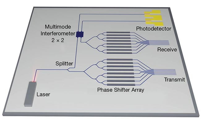
Figure 2. The schematic of a lidar PIC shows the individual components, or elements, including the photodetector; transmit and receive (TX and RX) paths; phase shifter array; laser source; and beamsplitter. A multimode interferometer is used as a coupling mechanism. Courtesy of Silicon Austria Labs.
Meet the authors
Tommaso Cassese is senior scientist —
integrated photonic technologies at Silicon Austria Labs GmbH, a research center focused on electronic-based systems. Since 2023, he has served as the technical coordinator for the Horizon project CoRaLi-DAR; email: [email protected].
Ion Vornicu is a staff scientist at Silicon Austria Labs GmbH. His work focuses on the analog mixed-signal and digital integrated circuits design for sensing solutions based on lidar and bolometric sensors and ultrasound transducers; email: [email protected].