Radar and optical sensors offer complementary views of hazardous materials.
David R. Flanders, the Instaar Group, Arthur H. Mengel, Video Display Corp., and B. Scott Terry, SpectroTech Inc.
Optical remote sensing exploits reflected and emitted light within and beyond the range detectable by the human eye, which is broadly 400 to 700 nm. Above this range is the infrared, from 700 nm to ~3 µm, which is perceived as reflected radiation, and then 3 to 100 µm, which is perceived as heat, or thermal radiation. Optical remote-sensing equipment detects light from about 400 nm to 14 µm and forms images (using software-generated false colors) that often reveal features that might otherwise be invisible.
Remote sensing has been used for many years, both from the sky and from space. Only recently, however, has the technology existed to simultaneously detect hundreds of wavelengths, called hyperspectral remote sensing, along with the algorithms to spectrally analyze the resulting images.
These capabilities enable users to identify — and discriminate between — objects in a scene based on how they reflect light, which is known as their spectral properties or fingerprint. For example, crop species and minerals can be identified; stressed field crops can be differentiated from healthy ones; narcotic crops can be spotted from the air; and environmental runoff can be observed and pollution sources traced. The applications are almost endless.
Radar-based remote sensing operates differently from the optical method. Rather than using sunlight as the source, radar generates pulses of radiation in the microwave portion of the spectrum (millimeter- and centimeter-scale wavelengths) that are transmitted from an antenna toward the object under study. The same antenna receives the reflected radiation.
The magnitude and phase of the reflected radiation allow panchromatic (gray scale) images to be built up as the antenna scans a scene. Because radar uses only one wavelength, it cannot reveal much about the physical properties of objects in the scene, other than by their reflective characteristics, or texture. Smooth roads and runways appear matte black, whereas metal or rough objects appear bright (Figure 1).
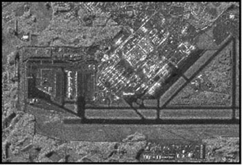
Figure 1. Radar-based remote sensors, which can operate in all weather conditions and at night, reveal information about an object’s reflective characteristics, or texture. The smooth roads and runways at this airport appear matte black, whereas metal or rough objects appear bright.
Compared with optical remote sensing, however, radar offers the advantage of operating in all weather conditions and at night. The two techniques can be complementary.
The resolution of radar remote sensing once was limited by the size of the antenna used to transmit and receive signals. For example, a radar device operating at a wavelength of 5 cm would require an antenna 5 m across to achieve a spatial resolution of 10 m at a range of 1000 m. At the same wavelength, achieving 1-m resolution requires a 50-m-wide antenna, which is clearly impractical.
Synthetic-aperture radar
Synthetic-aperture radar, however, can achieve high resolution by using relatively small antennae to simulate a much larger aperture (Figure 2). There are two ways to form the synthetic aperture: Use many small-aperture antennae, distribute them over a large area and combine their signals to form an image that appears to come from one large antenna; or put one small antenna in motion (on an aircraft or spacecraft), with the changing position over time simulating the span of a large antenna.
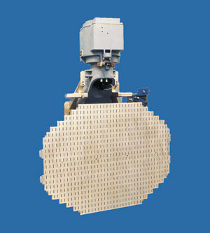
Figure 2. Synthetic-aperture radar devices achieve high resolution by using several relatively small antennae to simulate a much larger aperture.
The synthetic-aperture radar produced for the Group for Environmental Research measures 60 cm along the long axis, yet capable of 1-m resolution at up to 120 km. A modified commercial variant of the Lockheed Martin military APG-67 (E) radar, it has been produced for several years, is fully qualified as a multimode radar system and has flown on F-5 and F-20 aircraft as well as on commercial aircraft. It also has been successfully fused with hyperspectral technology from Texaco’s Alto Technologies division in Houston for oil spill surveillance, environmental baseline mapping, seep detection and resource exploration.
The main components of a hyperspectral imager are the scanner, which defines the spatial characteristics of the acquired images, and the spectrometer, which divides the energy from a pixel into its spectral components and transforms it into an electronic signal.
‘Whisk broom’ mapper
The scanner module is a “whisk broom” strip mapper. Based on the Collins scanner design, it consists of a multifaceted mirror that rotates, changing the field of view (Figure 3). The aircraft-mounted scanner acquires data along the flight path to form a scan line, producing a strip-map image.
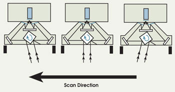
Figure 3. The scanner of a hyperspectral imager defines the spatial characteristics of the acquired images. The scanner module comprises a multifaceted mirror that rotates, changing the field of view as the aircraft carrying the device flies across its imaging target.
The spectrometer module is composed of different optical paths and provides many channels of spectral information, depending on the specific suite of multiband sensors used, including the far-looking infrared (30+ μm) sensor packages from Video Display Corp. of Birdsboro, Pa.
The scanner deployed for oil spill detection uses just three wavelength channels, while a scanner deployed in environmental baseline mapping can record as many as 200 channels. All channels of the source emission-profiling spectrometer are fully coregistered, ensuring accurate measurement of spectra within each individual pixel. As with the synthetic-aperture radar, the user operates the system via a simple graphical interface. System status may be monitored, real-time image data displayed and system parameters set from a simple menu-driven user interface.
Oil spill detection
Optical- and radar-based remote sensing techniques can be complementary for oil spill detection and mapping. In radar imagery, the gray levels of an object delineate its surface geometry: The rougher the surface, the brighter it appears in the image. On water, the wind and currents induce surface roughness. These effects are, however, reduced by the presence of a thin layer of natural or spilled oil.
Satellite radar imagery, although very valuable, is generally insufficient for routine monitoring of coastal regions for several reasons: The satellite may not be in the right place at the right time, the resolution may be too coarse (for example, the resolution of Radarsat-1 is 25 m), and the imagery is not available in real time.
Since 1977, all-weather detection of oil on the sea surface has been carried out from aircraft with side-looking real-aperture radars. These systems typically offer a spatial resolution of 50 to 75 m at a distance of 10 km from the aircraft and 100 to 150 m at 20 km.
Real-aperture radar is adequate for detection of oil on the sea surface but is unable to distinguish individual ships within close range of each other. For the use of remote-sensing data to be accepted as evidence in court, the oil spill in question must appear attached to the prosecuted vessel. Poor-resolution radar data often are, therefore, inadequate for prosecution. This is particularly true when several vessels covered by one single radar pulse are rendered as a target.
High-resolution synthetic-aperture radar, on the other hand, singles out the individual vessels and shows which one is attached to the oil. The GSAR system from the Instaar Group — a consortium of companies that is engaged in environmental research, image product development and resource exploration — has a spatial resolution of 3 m or better and, contrary to real-aperture radar, can be operated in strip-map mode or in spotlight-focusing mode with 1-m resolution.
Radar remote sensing can be operated at night and during inclement weather but is limited to operating within a range of wind speeds. As wind speed increases, the effect of the oil on the surface becomes less distinguishable; thus, oil spill monitoring using radar tends to be limited to a wind speed of 3 to 10 m/s.
Typically, the water surface appears black in a radar image if the wind speed does not exceed 3 m/s. In regions of higher wind speed — where the image still appears dark — the presence of some type of surface film may be inferred. This is the basis for the radar detection of oil slicks, such as when a tanker spilled thousands of liters of oil into Manila Harbor in the Philippines (Figure 4).
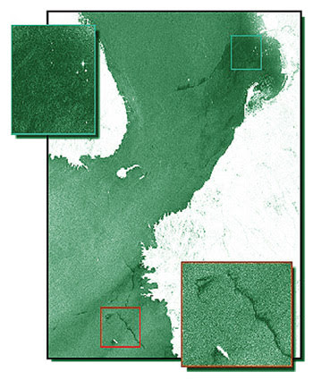
Figure 4. After a tanker spilled thousands of liters of oil into Manila Harbor in the Philippines, the Radarsat-1 satellite imaged the extent of the discharge. The dark area near the top of the bay indicates concentrated oil patches at the original location of the spill. Additional patches are near the bay’s entrance. Bright reflections in the image are from vessels in the harbor. This part of the world is particularly prone to cloud cover, and images such as this would be difficult to acquire using optical remote sensing or photographic techniques.
More detailed information
Radar also shows little about the makeup of the oil constituting the spill. This is where optical remote sensing can provide information that is complementary to that provided by radar.
Oil films on the water’s surface water are strong reflectors of ultraviolet light. By imaging the sea surface at short wavelengths, we can very clearly see oil films on the water. Moreover, with an instrument that simultaneously collects thermal (long-wavelength infrared) radiation, we can infer properties of the oil and its thickness. Thick oil has emissive properties different from thin oil and the surrounding seawater. By superimposing the thermal image of the oil slick on the ultraviolet image, the areas where the oil is thick enough to be recovered are easily seen (Figure 5).
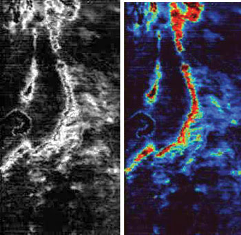
Figure 5. Infrared (left) and composite (right) images show an oil spill off the coast of Rhode Island. The red color in the composite image indicates the thickest layers of oil, while blue to green variations indicate a transition from denser to lighter layers. The wakes of several small boats are visible as snakelike patterns in the IR image, where they disturbed some of the surface components of the spill. Aerial photographs showed little evidence of the oil slick.
In 1999, Hurricane Floyd caused extensive damage to the eastern seaboard of the US. In North Carolina, the Tar and Neuse rivers overflowed their banks, displacing thousands of people from their homes. Potentially more devastating, however, was the effect the floodwaters had on the region’s agriculture — in particular, the interaction of the flood with the large number of hog farms situated along both rivers (Figure 6).
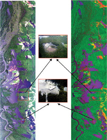
Figure 6. Hyperspectral imaging helped assess the contamination caused by hog waste along North Carolina’s coastal plain after a hurricane. The distinctive pink color seen in an unbreached lagoon is typical of water containing hog waste. The false-color image on the right shows the analysis of this particular region where land has been colored red and yellow, indicating that hog contamination has been identified by spectrally matching the pixels with the signature from the unbreached lagoon. Courtesy of Rick Dove.
Flood contamination
In North Carolina, farmers are allowed to store pig waste in open lagoons. After it is broken down anaerobically within the lagoons, the waste is used as crop fertilizer. During the hurricane, several lagoons were flooded or breached, and waste was spread over a significant area of the coastal plain region of the state.
Early consortium member companies, in collaboration with the state Division of Emergency Management and the Federal Emergency Management Agency, deployed a high-resolution airborne imaging system to help assess the effect of the flood and to investigate whether pig waste contamination could be detected spectrally from the air.
The hyperspectral imaging system collects spectral data in 31 bands in the visible, short-wave infrared and thermal wavelengths at resolutions up to 1 m, or in 11 bands at up to 0.5-m resolution. The equipment can display imagery as true color — that is, as if from an aerial camera — or as false color, where the colors can be used to indicate a specific feature in the scene.
Multispectral imagery was processed to differentiate the areas contaminated with the waste over the land and in the water. Identifying an unbreached hog lagoon in the digital image and then using the spectral signature of those pixels as a matched filter through the rest of the collected imagery data files isolated the spectral signature of the waste. Levels of approximately 15,000 counts per milliliter of coliform were measured in two regions of the river. Ground data from both soil and water samples verified the elevated levels of coliform.

Figure 7. In a different area of the coastal plain, water containing the spectral signature of fecal coliform has been colored purple. Ground data verified the elevated levels of coliform in the water.
In this case of assessing the damage caused by a natural disaster, hyperspectral remote sensing proved extremely useful, allowing the rapid survey of large areas of the state and indicating the extent of the problem caused by a specific contaminant. Indeed, because of the success of the Hurricane Floyd campaign, plans are being drawn up to use remote sensing to routinely monitor the environmental effects of the pig farming industry in North Carolina.
The Instaar Group’s flagship platform will be a British Aerospace Jetstream 31 twin-engine aircraft, equipped with a source/emission-profiling spectrometer hyperspectral imaging system, synthetic-aperture radar, forward-looking infrared and a microwave data transmission system. With the integration of this multisensor navigation and communications suite with Video Display’s quantum ferroelectric sensors and touch-screen displays aboard the aircraft, the consortium can deploy sensing operations on short notice to intercontinental locations while offering real-time downlinks to ground control locations.
The advent of extended infrared sensors, high-speed computers and sophisticated software processing algorithms has enabled a new generation of remote sensing systems. We can collect radar images at great distances and at high resolution from modest, lightweight systems. Optical scanners can collect hundreds of wavelengths simultaneously and track minute differences in spectral properties. Aircraft carrying remote-sensing equipment are able to survey many hundreds of square kilometers a day, with imagery available in real time on the aircraft so that cleanup efforts can be put in motion and polluters caught in the act.
Acknowledgments
The authors wish to thank John C. Petheram of Lockheed Martin’s space division, Ben M. Sorenson of BMS International in Naerum, Denmark, and Terence F. Melhuish of Transport Canada’s marine safety division for their valuable technical oversight.
Meet the authors
David R. Flanders is director of Instaar at Aydin Displays, a division of Video Display Corp. in Birdsboro, Pa.; e-mail: [email protected].
Arthur H. Mengel is director of Special IR&D projects at Video Display Corp. in Birdsboro, Pa., and Tucker, Ga.; e-mail: [email protected].
B. Scott Terry is co-founder and president of SpectroTech Inc. in Clemson, S.C., and strategic interface and marketing consultant to Bombardier Aerospace of Montreal; e-mail: [email protected].