Vyacheslav M. Ryaboy, Newport Corp.
With vibration-isolated platforms, questions of load distribution and static stability of pneumatic support systems are not always properly understood. This can create difficulties when setting up modern optoelectronic systems.
Optical tables on soft pneumatic supports are a staple of precision vibration control. Besides superb vibration isolation, they provide high load capacity that enables researchers to isolate large optoelectronic setups, including heavy elements such as cryostats, high-power lasers, atomic force microscopes, scanning tunneling microscopes and optical assemblies.

Figure 1. A microscope is set up on a pneumatically isolated optical table. Several factors – including static stability and load distribution – figure into the design of vibration-isolated systems. Images courtesy of Newport Corp.
When designing or specifying a vibration isolation system, the first step is to make sure that the loads on individual isolators are within allowable limits. All isolators are rated to certain maximum loads. Some models also have minimum recommended loads. Most designs of isolators – pneumatic in particular – are not intended to bear any negative (tensile) loads. The loads on each isolator should be estimated a priori.
Fortunately, state-of-the-art pneumatic isolation systems are always statically determinate, which makes the load calculation a simple task. They are equipped with leveling valves to set up the table in precise horizontal position, and maintain this position against changes in the payload or external perturbations. There are always three leveling valves, notwithstanding the number of isolators. This means that some of the isolators are slaved together; i.e., their air volumes are connected. When disturbed, they can freely trade air between themselves, so they do not offer any resistance to rotation about their common center. Standard ways of connecting the isolators in typical configurations are shown in Figure 2.
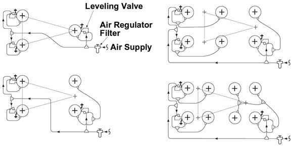
Figure 2. Schematics of pneumatic plumbing for systems of (a) three isolators, (b) four isolators, (c) six isolators and (d) eight isolators. Stability triangles are shown by dim lines.
The air pressure is the same in each isolator of the slaved-together group, so each isolator bears the same load and has the same stiffness. A group of slaved-together isolators is therefore statically equivalent to one isolator placed at its geometrical center, with the stiffness equal to the sum of individual stiffnesses. Consequently, there are always three effective support points, and the system is statically determinate.
To find the loads on each isolator, it suffices to solve three equations of equilibrium for the total loads on three groups of isolators and to divide by the number of isolators in the group. The center of gravity (CG) of the whole system of table and payload should always stay within the “stability triangle” in the horizontal plane. In a well-arranged system, loads supported by all isolators are within the allowable range and are, preferably, close to each other.

Figure 3. The concept of static stability.
There are two types of instability in pneumatic vibration isolation systems. First, the system can become statically unstable because its CG is too high. Second, it can become dynamically unstable because the leveling valves have the gains set too high. This article discusses mainly the static stability.
High-performance isolation systems are characterized by very low stiffness of the isolators. State-of-the-art pneumatic vibration isolation systems can have frequencies of natural vibrations as low as 1 Hz. That gives rise to potential static instability if the payload has a relatively high CG. Static stability should be analyzed before constructing the isolation system.
A general criterion is that a mechanical system in a position of static equilibrium is stable if any small deviation from this position causes its potential energy to increase (Figure 3). Usually, the potential energy is a quadratic function (quadratic form) of small deviations of its generalized coordinates from the equilibrium values. The equilibrium is stable if this form is positive.
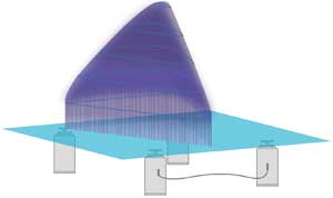
Figure 4a. Stability domain for the center of gravity of an isolated payload, including the tabletop, on a 4 x 8-ft table supported by four Newport S-2000 or I-2000 isolators in standard positions, two slaved along the front long side of the table. (Isolators are not drawn to scale.) The total load is 4000 lb, and the maximum height is 25.85 in. over the bottom surface of the table (represented by the light blue plane). The restriction on maximum admissible load per isolator is not taken into account in this picture.
Linear static and quasi-static stiffness of a pneumatic vibration isolator’s chamber is defined by the effective piston area, the total volume, and the gauge and atmospheric pressures. When estimating the stiffness of the isolator under small displacements for calculating the vibration isolation, usually the stiffness of the diaphragm is added. However, quasi-static disturbances may occur beyond the range of small displacements, usually spanning just a few microns. In this case, the diaphragm is rolling and does not provide additional stiffness. For a safe estimate, the stiffness of the diaphragm should be neglected when calculating the static stability.
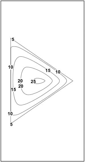
Figure 4b. Contour lines for Figure 4a. Heights are in inches.
To analyze the static stability, consider a small deviation from the equilibrium described by a small rotation around an arbitrary horizontal axis, and derive the change in the potential energy that is the sum of (negative) change in the gravitational energy and (positive) change in the elastic energy stored in isolators. This incremental potential energy is expressed as a quadratic form of two small angles of rotation around two perpendicular axes. This form must be positive, which leads to a criterion of stability. This criterion determines the maximum allowable height of the CG as a function of its position in the horizontal plane. Physically, there are two principal axes of rotation for any position of the CG in the horizontal plane: one with the maximum rotational stiffness, the other with the minimum rotational stiffness.
Stability requires that even for the minimum rotational stiffness, the increase in elastic energy must be greater than the decrease in gravitational energy for small rotations about the corresponding principal axis. Because the isolators are not designed to withstand tensile loads, the position of the CG is constrained in the horizontal plane by the stability triangle. The resulting stability domain for the CG is a dome-shaped area over the stability triangle that can be visually described as a “cross” of parabolic and pyramid shapes. It extends higher for stiffer isolators, lower for softer ones. An example of the stability domain for a typical table configuration is shown in Figure 4.
The maximum load on each isolator is limited, meaning that the CG of the whole system must stay close to the center of the table in the horizontal plane. Figure 5 shows the stability domain reduced, in comparison with Figure 4, by restricting the maximum load per isolator.
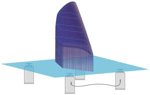
Figure 5. Same as Figure 4a, but the restriction on maximum admissible load per isolator (2000 lb) is taken into account.
Leveling valves can add some stiffness and improve the static stability, but this effect is usually small and can be neglected for safe design. On the other hand, the self-leveling system provides a feedback mechanism that can lead to dynamic instability. This phenomenon is defined by the gains of the leveling valves. It depends not only on the relative positions of the isolators and the system CG, but also on the mass distribution (moments of inertia) of the payload. If the system is only marginally stable statically, the valves should be closed or almost closed to maintain stability.
Meet the author
Dr. Vyacheslav M. “Slava” Ryaboy is principal mechanical engineer at Newport Corp. in Irvine, Calif.; e-mail: [email protected].
The procedure for determining and adjusting the load distribution and static stability of a pneumatic isolation system is as follows:
• Calculate the position of the center of gravity (CG), the loads on individual isolators and the stiffness of individual isolators for those loads.
• Estimate the static stability by comparing the height of the CG to the maximum allowed by the criterion of stability.
• If the loads on the isolators are outside the desired range, or the CG is too high outside the stability domain, the system should be modified by changing the master-slave arrangements between isolators, changing the positions or number of the isolators. In some cases, recesses, outriggers or cradle systems for isolators may be required.
• Repeat the calculations.
The static stability calculations can be performed by standard mathematical software along with calculation of loads on isolators. Excel and Mathcad worksheets are available for this purpose.