
Polymers and Liquid Crystals Harness the Power of Polarization Control
Polymers and liquid crystals are well-known materials that are critical to perform numerous optical applications. Their distinct properties make them materials of choice for polarization control and measurement.
TOM BAUR AND MICHAEL KRAEMER, MEADOWLARK OPTICS
In his early works on polarization, luminary physicist William Shurcliff offered a powerful sentiment: “If light is man’s most useful tool, then polarized light is the quintessence of utility.”
Considerable evidence, both in the form of applications and commercially available products and devices, suggests that Shurcliff’s assessment holds true. Optical materials and components that can control and measure polarization are critical enabling technologies.
Courtesy of iStock.com/Ad Gr.
Leading scientific figures throughout history investigated the polarization of light. One of the earliest methods for polarizing light used double refraction in calcite. The Danish physician Rasmus Bartholin achieved this demonstration in 1669. In 1808, French physicist Étienne-Louis Malus showed oblique reflection from a glass plate. However, calcite of optical quality is rare and limited in aperture to a few centimeters. Meanwhile, glass plate reflection is only a partial linear polarizer, except at Brewster’s angle of incidence, which is ~57° for common crown glasses.
Even when Jean-Baptiste Biot discovered in 1815 that tourmaline crystal could also be used in transmission as a linear polarizer due to its strong dichroism, the advancement again used a crystal that was not available with a large clear aperture.
More than 100 years later, Edwin Land pioneered the breakthrough that overcame the centuries-old bottleneck. Land developed the sheet-type polarizer in 1932, using, for the first time, a polymer, dyed polyvinyl alcohol, in a polarization optical component.
Today, sheet polarizers are essential to LCDs, including computer monitors and many mobile phone displays.
But even before achieving this level of ubiquity, Land’s breakthrough caught the attention of prominent physics minds.
“The most important event in the modern history of polarized light was the invention of the sheet-type polarizer,” Shurcliff said of Land’s milestone.
Polarization fundamentals
Polarizers are polarization selectors; they transmit or sometimes reflect one state of polarization and block an orthogonal state. Usually, these are orthogonal states of linear polarization, though they can be circular polarization states in certain cases.
Waveplates — polarization modifiers rather than polarization selectors — are another common and important polarization component. Early iterations of these components were made using calcite, quartz, or magnesium fluoride, but each of these materials were size-limited to ~15 cm or less and required precise polishing to tight thickness tolerances to achieve adequate performance. For quartz, the tolerance is often <±100 nm. For calcite, it is <10 nm. This makes these crystal waveplates too expensive for use in mass commercial markets.
Polymers and liquid crystals provide a solution for larger aperture and cheaper polarization modifier components. Polymers can replace static crystal waveplates in most applications. And liquid crystals, though most widely used in and for displays, achieve favorable performance in precision optical and laser applications. Liquid crystals also exhibit a useful property that enables low-voltage electrical control of a polarization state.
Profitability remains the driving force for developing high-quality polymer waveplates and liquid crystals, with a large commercial market enduring for numerous types of displays made from these materials.
The versatility of polymers
Several different polymers are used to fabricate waveplates. Polymers commonly used for this application include polyvinyl alcohol, polycarbonate, polystyrene, cyclic olefin copolymer, polyimide, and polymethyl methacrylate (PMMA). These materials are often made as cast films that are optically isotropic. They can be made birefringent by heating to a softening temperature and then stretching the material(s), which orients the long chain polymer molecules. The resulting anisotropy produces birefringence of an amount that depends both on the softened polymer temperature and the stretch percent amount.
Typical film thickness values range from 50 to 200 µm, and the produced birefringence delivers retardance values — the degree of angular shift in the phase of incoming polarized light — that can range from <10 nm to 3 µm. The birefringence is a function of wavelength in Figure 1 for polycarbonate. The general curve shape shown by Figure 1 is similar for most polymer films, except for polyvinyl alcohol, which has a much lower dispersion of birefringence.
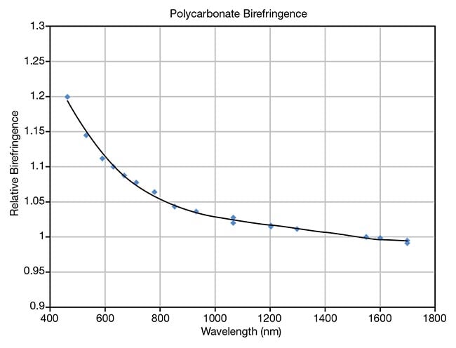
Figure 1. Birefringence, a function of
wavelength, is shown for polycarbonate.
The birefringence variation (with wavelength)
is normalized to unity at 1550 nm. The
birefringence value depends on stretch
process parameters. Courtesy of Meadowlark Optics.
The uniformity of retardance of the oriented films correlates to the thickness uniformity of the cast films. Figure 2 shows the transmitted wavefront distortion for a 50-mm aperture of a sample of 100-µm-thick PMMA film before stretching. Typically, this will improve (from about one wave at 632.8 nm) upon lamination between optically flat windows that possess a good index-matching adhesive. The wavefront distortion on this sample in Figure 2 implies a thickness variation of ~0.43 µm, peak-to-valley, ~0.43% of the film thickness. The retardance uniformity of the films is acceptable for most applications, although it is not necessarily desirable for more elaborate measures, such as polishing crystal quartz.
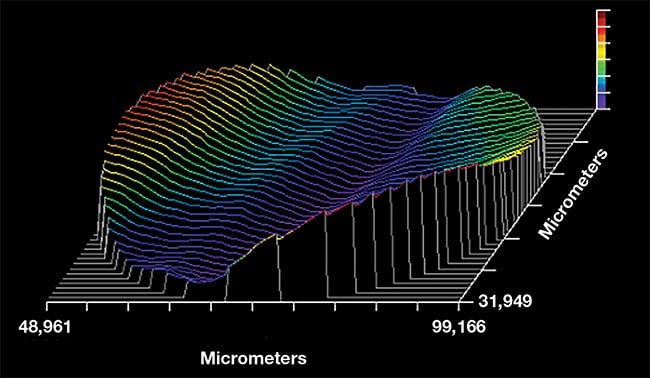
Figure 2. A transmitted wavefront distortion
profile for a 50-mm-diameter polymethyl
methacrylate (PMMA) film. Peak-to-valley
variation is one wave at a wavelength of
632.8 nm. Courtesy of Meadowlark Optics.
Figure 3 shows the measured map of spatial variation of retardance over a 105-mm-diameter aperture after stretching one of these polycarbonate films. The peak-to valley retardance variation is ~6.5° or 5% of the retardance. These values correspond to 158° at 640 nm. The fast axis direction variation is <0.25° peak-to-valley for this large waveplate film.
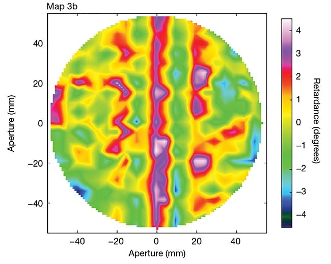
Figure 3. The adapted figure shows measured
retardance uniformity of an 11-cm-diameter
polymer waveplate, with an average retardance
of 157.7 nm at 633 nm. Courtesy of Meadowlark Optics via Journal of Astronomical Telescopes, Instruments, and Systems.
For comparison, a 4.2-mm-thick quartz waveplate of the same clear aperture has a retardance variation of ~0.008 waves or 2.9° at 631 nm, even though the thickness uniformity (inferred from the transmitted wavefront distortion) is 8 nm, and the physical wedge is 0.06 s. This thickness uniformity implies an expected retardance variation of 0.2° peak-to-valley, which is much less than the measured uniformity of 2.9°.
The degradation from the expected uniformity results from variations in the crystal birefringence, possibly due to stress built into the crystal during the growth process. The quartz waveplate is twice as uniform as the polymer one in this example, though the cost of manufacture is >10× higher for the quartz waveplate in small volumes.
Polymer properties
Beyond cost-effectiveness, polymer waveplates also offer a dramatically improved angular field of view compared with crystal waveplates. Figure 4 shows a comparison of the change in retardance with angle of incidence for a compound zero-order quartz waveplate, with a plate thickness of 1 mm to the true zero-order performance of a single polymer layer of 75-µm thickness.
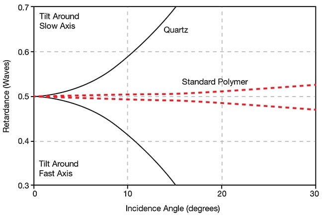
Figure 4. Graph data shows rays in a plane of
incidence containing either the fast or slow axis
of a waveplate. Rays entering the waveplate at
other azimuths will have a smaller change in
retardance with the angle of incidence. The
graph charts angular dependence of retardance
for the worst-case azimuth. Courtesy of Meadowlark Optics.
Compound zero-order waveplates are fabricated by subtracting two crystal waveplates, each with slightly different thicknesses. A true zero-order crystal waveplate is generally too thin and fragile to be practical to make or to handle. Figure 4 shows rays in a plane of incidence containing either the fast or slow axis of the waveplate. Rays entering the waveplate at other azimuths will have a smaller retardance change with the angle of incidence.
Layers of polymer waveplates can also be combined in different ways so that the resulting component can be made to be achromatic. Figure 5 shows the measured performance of a five-layer polymer achromatic waveplate. Further improvement is possible with more layers, as shown in the theoretical curves in Figure 6. While such a design architecture can be achieved using crystals, this is an expensive alternative. Also, the angular field of view is much smaller than when using polymer layers.
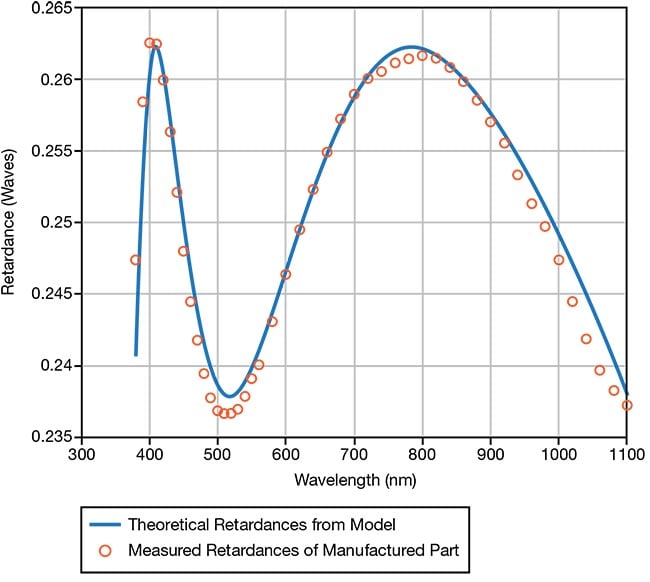
Figure 5. Retardance of a five-polymer layer
quarter-wave waveplate. Courtesy of Meadowlark Optics.
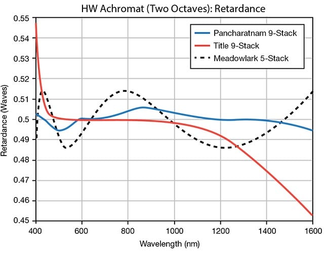
Figure 6. Modeled performance of different
multilayer achromatic half-wave (HW)
waveplates. Whereas Figure 5 shows the measured performance of a
five-layer polymer achromatic waveplate,
further improvement can be achieved upon
the addition of layers, as shown in the
theoretical curves. Courtesy of Meadowlark Optics.
The measured damage threshold for laminated polycarbonate films is >500 W/cm2 at visible wavelengths, which is lower than that for crystal quartz. However, the thermal dependence of retardance is higher for crystal quartz at ~0.1% per degree Celsius versus 0.027% per degree Celsius for polyvinyl alcohol and .015% for polystyrene. Retardance decreases with heating in crystal quartz and polystyrene but increases in polyvinyl alcohol. These values are measured near room temperature but are nearly linear over a range of 20 °C.
Polymer waveplates can be a spin-coated layer applied to an optically flat window, or even to another element in an optical system, such as a mirror or a lens. These coatings are typically <10-µm thick and are comprised of a reactive mesogen. These reactive mesogens are liquid crystals that can be polymerized to form a high-molecular-weight polymer. They are coated over a photoalignment layer or a buffed polyimide alignment layer photopolymerize, in situ. The result is thin optically birefringent polymers, with ultraviolet light then delivered to cross-link the mesogen monomer.
Moreover, such waveplates can be patterned in their waveplate-axis direction when photoaligned. Patterning in this way into fine scale-diffractive waveplates provides useful functions, such as nonmechanical beam steering over large angles requiring power in the range of 10 V.
Laminating polymer waveplates between optically flat windows considerably reduces transmitted wavefront error. It also reduces spectral fringing in both the transmission spectrum and the retardance spectrum, both of which are undesirable. The fringe amplitude is largest for collimated light and is smaller in imaging beams. In addition, the error that results from the deviation from the expected retardation can be quite large — for example, 7% for an unlaminated polyimide quarter-wave waveplate film of 100-µm thickness.
Liquid crystal waveplates
Liquid crystals can be aligned into a waveplate-suitable configuration to mimic the molecular ordering of uniaxial crystals, such as quartz, magnesium fluoride, and sapphire. They can act as variable waveplate devices with low-voltage electrical control of the effective birefringence, and low-voltage electrical control of the retardance value as a result. This low-voltage electrical control has obvious advantages compared with mechanical motions of polarization optical elements for changing polarization.
The response times of nematic liquid crystals — liquid crystals in what is considered the simplest liquid crystalline phase — are typically a few milliseconds, with faster responses to increasing voltage than to decreasing voltage (Figure 7). Response time is proportional to the square of the liquid crystal layer thickness and therefore to the zero-voltage retardance of the liquid crystal cell. The response times for the two voltage directions for half-wave switching at 633-nm wavelengths are 7 ms and 1 ms for Meadowlark’s most-used nematic liquid crystal offerings.
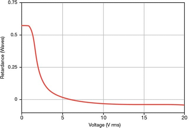
Figure 7. The response of a typical nematic
liquid crystal to an applied 2-kHz square wave
voltage. The response times of nematic liquid
crystals are typically a few milliseconds, with
faster responses to increasing voltage.
Response time is proportional to the square of
the liquid crystal layer thickness, and therefore
to the zero-voltage retardance of the liquid
crystal cell. RMS: root-mean-square(d). Courtesy of Meadowlark Optics.
Response times can be improved by using higher birefringence liquid crystals, which allows for a thinner liquid crystal layer. Common nematic liquid crystals have a birefringence between 0.1 and 0.2, and the dispersion of birefringence is similar in nature to that of polymers (Figure 1). Response times for half-wave switching are reduced to <150 μs in both directions by using higher birefringence liquid crystal and special voltage driving techniques. The resulting rise and fall response times are 32 μs and 139 μs, respectively, for half-wave switching at 532 nm.
The liquid crystal devices described here are often combined with other optics to perform functions through nonmechanical polarization control, for example, the rotation of a plane of linear polarization through any angle by the addition of a quarter-wave waveplate. Additional examples are the optical shuttering by the addition of input and output polarizers; the spatial modulation of either phase or amplitude of reflection from a spatial light modulator; and/or measuring polarization of a light beam.
A liquid crystal device can also combine with a polarizer. A useful example of this combination is to vary transmission or reflection.
Liquid crystals can also be used to dynamically generate holograms: In this application, the input light is polarized parallel to the liquid crystal director. These devices, liquid crystal on silicon spatial light modulators, have a 2D pixelated silicon reflective backplane usually with a pixel count of >1 million. Voltage changes to the pixels change the index of refraction in the liquid crystal layer, producing a reflected wavefront shape change. Frame rates here can be as high as 1 KHz.
The future of optical devices
Polymers and liquid crystals have become indispensable materials for developing optical devices for polarization control and the measurement of polarization. The development of consumer products for displays has advanced the quality of the available materials and made them viable options for laser systems, precision optical systems, and research applications.
Notably, in most cases, the functions enabled by these materials cannot be accomplished via commonly used alternative materials or devices. Meanwhile, when physically viable alternatives exist, these solutions are often too costly to carry out in mass.
Meet the authors
Tom Baur is the founder and board chairman of Meadowlark Optics. He focuses on product development, bringing new materials to the photonics community for polarization control and improving metrology for polarization components; email: [email protected].
Michael Kraemer holds a master’s degree in mathematics and doctorates in both physics and mathematics. He has worked as a software engineer for 24 years. His research interests include tunable filters, ellipsometry, and achromatic polarization devices; email: [email protected].
Acknowledgment
Figure 3 Attribution: The complete rectangular map, measured by Meadowlark Optics, is represented in Figure 32(a) from SPIE JATIS, 6(3), 038001 (2020). https://doi.org/10.1117/1.JATIS.6.3.038001.2. Notice: Reprinted under Creative Commons License CC BY 4.0, see https://creativecommons.org/licenses/by/4.0/.
Reference
1. D. Harrington et al. (2020). Polarization modeling and predictions for Daniel K. Inouye Solar Telescope, part 6: fringe mitigation with polycarbonate modulators and optical contact calibration retarders. J Astron Telesc Instrum Syst, Vol. 6, No. 3.
/Buyers_Guide/Meadowlark_Optics_Inc/c9201
Published: September 2024
Glossary
- optical materials
- Optical materials refer to substances or compounds specifically chosen for their optical properties and used in the fabrication of optical components and systems. These materials are characterized by their ability to interact with light in a controlled manner, enabling applications such as transmission, reflection, refraction, absorption, and emission of light. Optical materials play a crucial role in the design and performance of optical systems across various industries, including...
- polarization
- Polarization refers to the orientation of oscillations in a transverse wave, such as light waves, radio waves, or other electromagnetic waves. In simpler terms, it describes the direction in which the electric field vector of a wave vibrates. Understanding polarization is important in various fields, including optics, telecommunications, and physics.
Key points about polarization:
Transverse waves: Polarization is a concept associated with transverse waves, where the oscillations occur...
- wave plate
- An optical element having two principal axes, slow and fast, that resolve an incident polarized beam into two mutually perpendicular polarized beams. The emerging beam recombines to form a particular single polarized beam. Wave plates produce full-, half- and quarter- wave retardations. Also known as retardation plate.
- liquid crystal
- Liquid crystals are a state of matter that exhibits properties intermediate between those of conventional liquids and solid crystals. In a liquid crystal, the molecules are ordered like those in a crystal, but they can still flow like a liquid. This unique combination of structural order and fluidity gives liquid crystals their distinctive characteristics and makes them valuable in various technological applications, particularly in display technology.
Key features and characteristics of...
Featuresoptical materialsOpticspolymersliquid crystalscomponentswaveplatesMeadowlark Opticstom baurMichael Kraemerpolarizationwave plateswave plateliquid crystal