Dave Arnone, Aaron Van Pelt and Kathy Li Dessau
With the shift to tighter integrated circuit manufacturing specs and 157-nm lithography, motion control increasingly demands high resolution and long-term stability not found with conventional motors.
Motion control applications
in the semiconductor manufacturing industry range from mask and wafer alignment
to laser beam steering and active pointing stabilization. Because these applications
are “set and hold,” with position first optimized and then maintained
for a certain length of time, they demand high resolution and long-term stability.
Positioning accuracy, the traditional emphasis of motion control systems, is less
important in this environment.
This increasing emphasis on resolution and stability
will only continue with the trend toward manufacturing of tighter-geometry integrated
circuits and the shift from 248-nm lithography (with a KrF excimer laser) to 193-nm
(with an ArF excimer laser) and now to 157-nm processing (with an F2 excimer laser).
Processing at shorter wavelengths also
dictates that motion control systems be exceptionally clean to eliminate contamination
of the optics, wafer and mask. Any inorganic and organic compounds introduced into
the air from the mechanical or optical components are broken down by the high-energy
UV beam and deposited on the optics surfaces.
The UV beam polymerizes any surface
contaminants, introducing a high-heat-capacity site that in turn burns the optical
coating. A cleanliness benchmark, where the outgassing level of organics and inorganics
is compatible with the UV beam environment, is vacuum compatibility to 10—9 t, although
10—6 t may be adequate in some instances.
Today’s semiconductor-targeted
systems must deliver vacuum compatibility as well as excellent resolution and superior
long-term stability. For electron-beam mask-writing systems where magnetic elements
steer the beam, the motion control systems also must be highly nonmagnetic. Manufacturers
must build them using materials such as titanium and molybdenum to minimize the
magnetic properties.
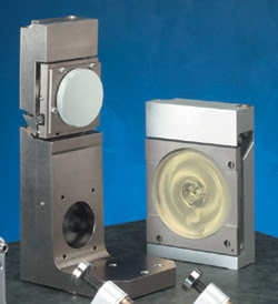
Figure 1. Stick-slip piezo-based motion
control systems can be a good fit for semiconductor applications.
Until now, stepper motors, DC servomotors
and ferroelectric actuators (i.e., piezoelectric or electrostrictive) have dominated
the traditional motion control market. Designed for the industrial manufacturing
environment, these devices provide the repeatability and accurate automation required
for processes such as cutting and welding. Most, however, do not offer good long-term
stability and/or cannot be made vacuum-compatible or nonmagnetic. Thus, a better
fit for semiconductor applications may be piezo-based systems. These systems can
hold their position with no applied voltage or brake, deliver high stiffness (thus,
long-term stability) and provide step sizes in the range of tens of nanometers.
They also can be manufactured cost-effectively to be nonmagnetic and vacuum-compatible.
Piezo-based motors
Piezoelectric motion control devices have been
around for many years. In the simplest case, the piezoelectric material simply expands
and contracts under applied electrical voltage to provide the positioning mechanism.
Such a device is very fast and provides extremely fine control but has a limited
travel range. Often it is integrated in-line with a screw to boost the range of
motion (Figure 2). The problem is that material expansion is a direct measure of
applied voltage, and constant power must be applied to hold the adjusted position.
Piezo systems also typically suffer from hysteresis and creep (also known as low
stiffness), and require a clean, low-noise power supply for accurate positioning.
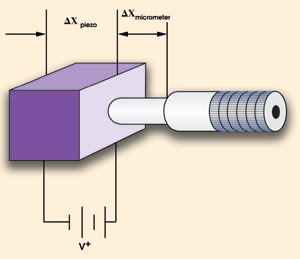
Figure 2. A conventional piezo-driven actuator’s extension is the sum of the extensions of the piezoelectric material and the micrometer.
Even though they can be both vacuum-compatible
and nonmagnetic, their limited travel range, poor long-term stability and need for
constant applied voltage have made them less desirable for precision set-and-hold
applications such as those in the semiconductor industry.
The piezoelectric transducer also is
seen in other configurations where movement does not rely solely upon expansion
and contraction for positioning. These stick-slip motors rely on the basic difference
between static and dynamic friction. One example of this principle is the tablecloth
trick in which a quick pull leaves the dishes on the table (low dynamic friction),
while a slow pull of the tablecloth carries the dishes with it (high static friction).
These nontraditional piezo motors use slow motion to move, turn or slide along objects,
and fast motion to return to their original position, thereby providing both high
resolution and long travel. Many can be nonmagnetic and vacuum-compatible as well.
One of the first examples of stick-slip
piezo motors uses multiple piezo elements to move a shaft in a manner similar to
that of an inchworm. These devices have an extension actuator and two clamps that
move in a synchronized clamp-extend/clamp-retract cycle. They deliver nanometer
resolution, long travel ranges and fairly high velocities of a few millimeters per
second. However, because the piezo is used to clamp the shaft, holding position
requires that the power be on, which could compromise long-term stability. Furthermore,
because the piezo is the holding element, it does not deliver the stiffness often
required in semiconductor applications.
Another nontraditional piezo-based
configuration applies an ultrasonic frequency to a piezo beam, generating a planar
elliptical path of the piezo tip. By using a spring to hold these piezo vibrators
against a ceramic strip fixed to a base, these vibrators will “walk”
with respect to the base. Often these motors are embedded in a sliding stage.
Because they combine high speed —up
to 250 mm/s — with very high resolution, the devices are best-suited for applications
requiring fast motion. An advantage is that they can be designed with enough force
to allow wobble-free positioning when not energized. However, the holding force
between the piezo beam and the ceramic strip limits long-term stability, and stiffness
is relatively low because the piezo is the holding element.
Finally, a third stick-slip design,
called the Picomotor, uses a piezo element to turn the screw. The piezo is positioned
between two jaws to provide the torque to turn the screw (Figure 3). Here, the piezo
is used only to turn the screw and not to hold the adjusted position. Thus, the
mechanical stability of the motor is identical to a nonmotorized screw and nut set,
delivering high stiffness and long-term stability.
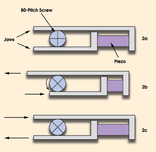
Figure 3. In a stick-slip motor that uses piezos to turn a screw,
two jaws grasp an 80-pitch screw (2a), and a piezoelectric transducer slides them
in opposite directions. Slow action of the piezos causes a screw rotation (2b),
while fast action causes no rotation (2c) because of inertia.
The working principle behind this stick-slip
motor is similar to how a person turns a screw. Two jaws, connected to either end
of a piezoelectric transducer, grasp an 80-pitch screw. A slow-rising electrical
signal applied to the piezo slowly changes its length, causing the jaws to move
in directions opposite and tangential to the screw, just as a thumb and forefinger
would. This slow motion makes the screw turn by static friction. At the end of the
transducer motion, a fast-rising electrical signal quickly returns the jaws to their
starting positions. Because of the screw’s inertia and low dynamic friction,
it remains motionless, holding position. Simply reversing the order of fast and
slow pulses reverses the direction of the motor.
The main advantages of such a device
include high stiffness and resolution, as well as long travel ranges. Because of
the slip-stick nature of the motion, though, the device tends to be slower than
the other types of actuators. Nevertheless, the system can be vacuum-compatible
(10—6 t) and nonmagnetic. Because the screw-based stick-slip motor relies upon the
mechanical properties of the screw, it can optimize set-and-hold applications, providing
a combination of submicron resolution and long-term stability.
Semiconductor manufacturing
One set-and-hold application using a compact stick-slip
motor involves the Z/tip/tilt platform of a scanning X-Y stage for semiconductor
wafer inspection, processing and microscopy. A fast X-Y stepper or servo system
scans the wafer or sample under inspection. Then three compact stick-slip motors
provide the final precision adjustment to align orientation and focal height (Figure
4). These three adjustment actuators sit on the scanning X-Y stage and are periodically
updated, then held constant over significant time intervals.
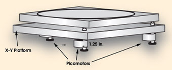
Figure 4. The high-speed translation stage uses three Picomotor products to adjust the height, tip and tilt.
Because of the critical alignment needs,
these actuators must keep their positions over the scan. Thus, this particular semiconductor
application requires compact, stiff, stable high-resolution actuators capable of
setting and maintaining position to tens of nanometers even with no applied power.
In addition, the motors must have low mass because they must sit directly on the
high-speed moving translation system. DC servomotors and steppers are too large,
while traditional piezo motors have too much creep and hysteresis. In this electron-beam
application, though, the motors had to be custom-made to be vacuum-compatible and
nonmagnetic.
Compact stick-slip motors also can
counteract laser drift in industrial metrology applications. Actively stabilizing
the laser can significantly improve system metrology. In this example, the laser
stabilization technique continuously stabilized a UV laser beam’s location
and pointing in an advanced reticle contamination inspection station. Here, the
beam left the laser and went through two motorized mirror mounts prior to reaching
the work site (Figure 5). Constant beam pointing was possible with the adjustment
of two mirror mounts. P1 and P2, the two points in space through which the laser
beam will propagate, were imaged on quadrant detectors called QD1 and QD2, respectively.
In turn, the system used the detected signals to servo the beam’s location
and pointing. By keeping P1 sufficiently close to a location called M2 and far from
P2, the system allowed treating the sampled legs independently.
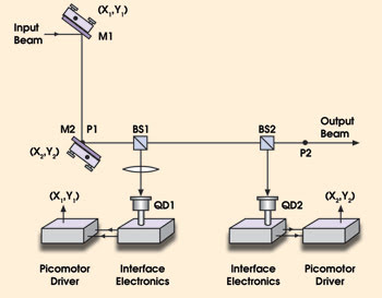
Figure 5. In this feedback system, points P1 and P2 define the two
points in space through which the laser beam will propagate.
Because the adjustments were made only
occasionally, this manufacturer required devices with superior long-term stability.
Moreover, the optomechanical modules that were used to steer the UV beam had to
provide high flatness, stability and reliability. New Focus engineers designed them
to conform to these critical specifications, allowing development of a custom bonding
process that could withstand the exceptionally clean environment yet not induce
optical distortion.
Meet the authors
Dave Arnone is mechanical engineering manager,
and Aaron Van Pelt and Kathy Li Dessau are product managers at New Focus Inc. in
San Jose, Calif.