As optical networks implement higher bit rates and move to denser channel spacings, new challenges for component testing emerge.
E.U. Wagemann and Gunnar Stolze
Fiber optics technology has taken a major leap forward with dense wavelength division
multiplexing (DWDM). Today, as networks move to speeds as high as 40 Gb/s, with
channel spacings of 25 GHz and below, time-domain properties of the signals become
increasingly important. As a consequence, modern optical components must be specified
for spectral and polarization-dependent loss, group delay and differential group
delay.
Because narrow-channel loss characteristics produce
steep dispersion characteristics, wavelength-selective devices challenge today’s
applied methods of determining dispersion properties. Therefore, the precise characterization
of these components requires a test method with high accuracy, high resolution and
a large dynamic range for both loss and dispersion.
Agilent Technologies has developed
a method that combines a tunable laser source with a low-noise output for loss measurements
and swept homodyne interferometry for the measurement of dispersion properties.
Using homodyne interferometry, group and differential group delay can be determined
by measuring the phase delay through the device under test.
The road to 40-Gb/s networks
The need to provide higher bandwidth over a single
fiber can be satisfied by different means. First, the deployment of additional wavelength
bands can increase spectral bandwidth. Second, more and more channels can be squeezed
onto a single band, decreasing channel spacing. Third, each channel can be modulated
at a higher speed — 10 and 40 Gb/s are key here.
The deployment of 40-Gb/s networks
presents a challenge to systems providers, network equipment manufacturers and component
manufacturers — and thus to test and measurement systems.
At higher data speeds and narrower
channel spacing, the “run time” properties of the signal as well as
loss become important. As a rule of thumb, one-tenth of a bit period is an acceptable
delay (or dispersion) for a system. For example, a bit period for 40 Gb/s is 25
ps, so 2.5 ps is an acceptable system delay. But a system has many components, so
the delay contribution of each component must be smaller. New techniques, such as
forward error correction, dispersion compensation, specialty fiber and digital postprocessing,
will be essential in achieving 40-Gb/s networks because they allow additional margins
for error-free data transmission.
Nevertheless, passive components are
at the front line of the network and, as such, are crucial to performance. Therefore,
the development of new methods for component testing is imperative.
Most passive components, such as fiber
gratings, arrayed waveguide gratings and add/drop modules, either route or drop
light. Excluding dispersion properties, compromises in the loss performance of these
components are unacceptable. In advanced networks, components can lead to system
penalties or even failure by not meeting the specifications of insertion and polarization-dependent
loss, and of group and differential group delay. The ability to test all these parameters
will be essential in passive optical devices, particularly at 10 and 40 Gb/s.
Testing for loss
Measurements of loss and dispersion traditionally
have been treated as separate tasks and have been addressed by separate solutions.
A fundamental shift in test instrumentation is needed to realize all-parameter analysis,
wherein both loss and dispersion parameters are measured simultaneously with the
highest possible accuracy. For advanced networks, test and measurement must precisely
characterize all relevant device parameters, rather than a limited subset or single
parameter.
Optical components are always tested
for loss. For wavelength-dependent components, such as optical filters and multiplexers,
spectral loss measurements determine the higher-order parameters that describe the
quality of the optical filter, including its shape, bandwidth, crosstalk and passband
ripple.
Passive components route, redirect
or block light channels. Because their main purpose is wavelength routing, they
must be characterized precisely for their spectral loss properties. Historically,
DWDM components have been tested with a broadband source and an optical spectrum
analyzer. Today, this commonly is addressed using a tunable laser and a power meter.
To gain higher dynamic range and resolution, tunable laser sources have become the
focus of considerable research.
Polarization-dependent loss
Tunable lasers with greatly reduced source spontaneous
emission are commercially available. An improvement of more than 30 dB in the ratio
of signal to total source spontaneous emission (compared with that of a typical
tunable laser) enables the use of a simple, broadband power meter rather than a
wavelength-selective receiver. A laser with low source spontaneous emission offers
an improved measurement range compared with a standard design when a power meter
is used as the receiver.
Because polarization is not fixed in
optical networks, polarization-dependent loss has become more and more important.
It represents the influence of polarization on the loss properties of optical components.
Higher-order parameters of optical filters such as bandwidth, passband ripple or
crosstalk also are polarization-dependent.
A typical measurement setup uses a
source (a tunable laser source, if this loss is to be measured over wavelength),
a polarization controller, the device under test and a power meter. The state of
polarization is changed, and a series of measurements are performed to evaluate
the polarization dependence of the device.
There are two approaches to these measurements: deterministic and nondeterministic. Deterministic techniques derive the device’s loss from its Mueller or Jones matrices, which are obtained by
measuring the transmission properties of the device over a set of defined input
polarization states. In contrast, nondeterministic techniques measure the minimum
and maximum transmission through the device over a large number of input polarization
states.
Using the “polarization scanning”
technique, the device is exposed to all states of polarization, and a power meter
measures the transmission. The maximum and minimum transmission through the device
can be measured directly, and the polarization-dependent loss is the ratio of
minimum and maximum transmission.
This technique is suitable for measurements
at a few wavelengths because the scanning is performed at each wavelength individually.
Exposing the instrument to all states of polarization is impossible because only
a finite number can be approached. In practice, a large number of polarization states
are generated at a scan rate that is suitable for the power meter’s averaging
time. Increasing the measurement time, which allows the transmission through the
device to be measured at more polarization states, reduces the uncertainty of the
measurement.
The Mueller method, a deterministic
measurement method, ascertains the loss by exposing the device to four well-known
states of polarization. This is advantageous if the loss must be measured over wavelength
with high resolution. The four polarization states typically are linear horizontal,
linear vertical, linear +45° and right-hand circular. The Mueller matrix coefficients
yield the average insertion loss, the minimum and maximum transmission, and, therefore,
the polarization-dependent loss.
This method can be incorporated with
transmission measurements over wavelength, where, at each of the four polarization
states, the transmission over wavelength is recorded. Consequently, the Mueller
method obtains accurate results in a very short time for a large number of wavelength
points.
Although they are based on different
approaches, both polarization scanning and the Mueller method should yield the same
results. Both methods demonstrate that they can measure low polarization-dependent
loss values, and the results over wavelength are in agreement. Measurement time
becomes the dominant criterion for choosing the appropriate method.
The Mueller method has an advantage
over polarization scanning because of its deterministic nature, which allows polarization-resolved
measurements to be performed. In integrated optical components, such as arrayed
waveguide gratings, two fundamental modes of propagation exist. These modes correspond
to two orthogonal states of polarization. Lightwave signals with other states of
polarization can be resolved into these fundamental modes, and the results of the
Mueller method can be analyzed to yield the spectral loss at these modes.
Testing for dispersion
In high-speed optical networks, the “timing”
properties of signals or parts of signals become important, making a precise characterization
of dispersion properties of optical components necessary. Dispersion may be managed
or compensated using special fibers or components, but a precise design for lowest
dispersion and a precise characterization of all components is required.
Three dispersive phenomena are known
to degrade network performance by broadening the digital pulses. In each phenomenon,
the degradation is caused by a difference in arrival time of various components
of the signal: spatial modes, colors or polarization modes.
Modal dispersion affects only multimode
systems. Most networks use single-mode fibers, so this dispersion effect is of little
concern.
Dispersion is observed when the index
of refraction varies with wavelength, causing changes in the group velocity. A variation
of group delay with wavelength causes delays in different frequency components of
the signal by different amounts, stretching a light pulse as it travels along a
fiber.
Polarization mode dispersion becomes
a performance limitation in high-speed systems when special fibers or devices have
compensated for chromatic dispersion. Pulse spreading is caused by the difference
in propagation velocity between orthogonal polarization states.
It is important to note that the structure
of a passive component itself can induce dispersion. In complex structures, such
as multilayer films or arrayed waveguide gratings, in which multiple paths are possible,
the addition of the various paths depends on the phase of the interference so that
the combined “effective path length” can be wavelength-dependent.
Today, modulation phase shift is the
standard method for measuring chromatic dispersion. A CW light source is intensity-modulated
by a high-frequency sine wave. The modulated optical signal travels through the
device under test and is demodulated by the receiver. The phase of the detected
modulation is measured relative to the original electrical signal. Relative group
delay is calculated from the variation of this phase with wavelength.
This method was first used to characterize
fiber properties and can be used to measure various components. It is most accurate
at the highest modulation frequencies — typically, frequencies in the gigahertz
range are applied. The offset between the main signal and the side modes is determined
by the modulation frequency: If the device’s dispersion properties vary in
a scale comparable to the modulation signal bandwidth, the resolution of modulation
phase shift is limited. This can happen for so-called group-delay ripple and at
the edges of a passband filter.
Swept homodyne interferometry
Narrow-channel devices challenge today’s
methods of determining dispersion properties because narrow-channel loss characteristics
go hand in hand with steep dispersion traces. For advanced components, test requirements
are therefore best described as “high accuracy, highly dynamic and high resolution”
— for both loss and dispersion. To address this properly, our setup combines
a tunable laser source with low-noise output for loss measurement and swept homodyne
interferometry for the measurement of dispersion properties.
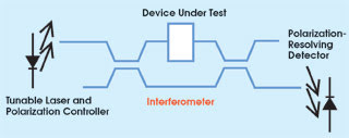
Figure 1. A typical optical setup for measuring dispersion properties using swept homodyne interferometry requires no moving parts.
In swept homodyne interferometry, a
laser source is wavelength-tuned, while the arm lengths of the interferometer remain
fixed (Figure 1). One arm includes the device under test, and the second is used
as reference. The optical signals are combined, and a diode detects a fringe pattern.
No moving parts are needed for the optical setup, which can be extended easily to
measure both the transmission and reflection properties of devices.
Interferometric pattern
This results in an interferometric pattern in
the detector plane. The phase information of the device is extracted by mathematical
means and translated into group delay.
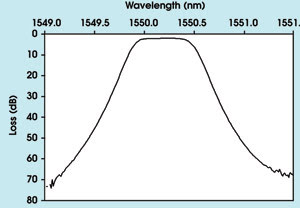
Figure 2. To demonstrate the ability to measure spectral insertion loss, a thin-film filter was used as the test device.
Swept homodyne interferometry acquires
dispersion information with high-spectral resolution as the phase information of
the device under test is obtained from a single wavelength. We have used the group
delay characteristics of a hydrogen-cyanide gas cell peak to check the capabilities
of this method. Gas cell peaks are based on molecular absorption lines and are used
for wavelength calibration because of their narrow spectral width.
The technique’s high sensitivity
is attributable to the fact that it compares optical, not electrical, phases. Because
all lightwave signals travel as a group, and not at a single frequency, group delay
is the parameter of interest. The group delay unit of measurement is time, usually
measured in picoseconds. It can be calculated from the phase delay using the formula

and is a measure of how much a light
pulse is stretched when passing a component. Differential group delay is a measure
of the polarization dependence of group delay — so there is a similar correlation
as between loss and polarization-dependent loss.
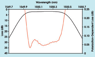
Figure 3. The polarization-dependent loss of a 100-GHz thin-film filter (insertion loss for reference) was determined using the Mueller method.
In our setup, a polarization controller
and a polarization-diversifying receiver record two traces of group delay, leading
to a Jones matrix as a function of wavelength. From this, maximum and minimum group
delay can be determined. This procedure ensures that the recorded group delay trace
is always free of polarization effects that can result, for example, from a change
in the input polarization state between two measurements.
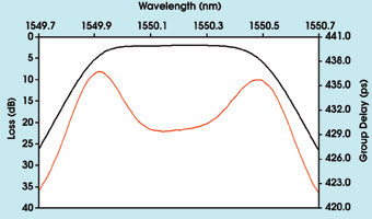
Figure 4. The group delay of a thin-film filter vs. wavelength has a typical double-dent structure.
To demonstrate the capability of the
technique, a thin-film filter was selected as a device for the all-parameter test.
These devices use a stack of layers with different optical path lengths for wavelength-selective
transmission and reflection properties. The tunable laser/power meter approach can
achieve a dynamic range of 70 dB (Figure 2). In the filter’s passband (approximately
400-pm-wide), the polarization-dependent loss was determined to be flat, as designed
(Figure 3).
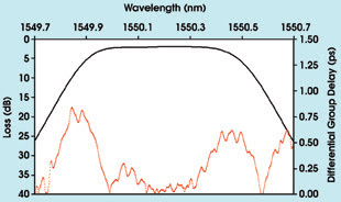
Figure 5. The differential group delay is designed to be close to zero in a filter’s passband.
The group delay of a DWDM filter should
be flat over wavelength and should have only small ripples because dispersion effects
resulting from ripples cannot be compensated in long-haul networks (Figure 4). The
differential group delay of a DWDM component is designed to be close to zero. This
would imply no polarization dependence of group delay. Good components display values
well below 1 ps in the passband of the filter (Figure 5).
Meet the authors
E.U. Wagemann is product manager at Agilent Technologies’
Optical Communications Measurement Div. in Böblingen, Germany, where he is
responsible for advanced measurement solutions.
Gunnar Stolze is an applications expert
at Agilent’s Optical Communication Measurement Div., specializing in optical
component testing.