An optical system is athermalized if its critical performance parameters (such as modulation transfer function, back focal length and effective focal length, etc.) do not change appreciably over the operating temperature range.
Janos Engineering, Janos Technology LLC
For rotationally symmetric optical systems, either the lens or the detector moves along the optical axis to maintain optical performance. If the compensating axial motion is accomplished without the use of motors or other active devices, then the optical system is considered passively athermalized. This article will discuss the consequences of uniform temperature fluctuations only and will ignore the impact of temperature gradients within the optical system.
The coefficient of thermal expansion (CTE) and the thermal coefficient of refraction (TCR) are material properties of lenses and housings that respond to temperature changes within an optical system. The following parameters change as a result of uniform temperature variations: radii of curvature, refractive index of the lens material, refractive index of the lens medium (usually air), mechanical dimensions of lenses and the physical dimensions of the lens support structure. The parameter variations with respect to temperature are detailed in Table 1.
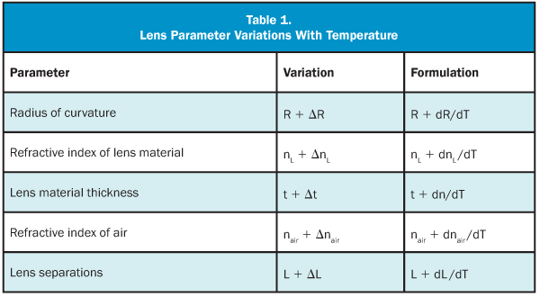
Passive athermalization is beneficial in optical systems that are isolated from direct human contact or have limited access to power. Systems that are deployed in space, for example, cannot afford to use the limited battery or solar power to energize motors necessary for maintaining focus. Additionally, motors have limited lifetimes, add weight to launch payloads and cannot be easily serviced once deployed in space. Therefore, it is undesirable to use them unless absolutely necessary.
As thermal sensors decrease in price, the deployment of thermal cameras for security applications will become prevalent. Security applications that need inexpensive lenses to deploy more systems require passive athermalization. These lenses are located on poles and are permanently mounted to structures that are inaccessible for refocus as temperatures change. The identification of items in the field of view relies on these passive mechanisms.
Hazardous environments can be encountered when performing tasks such as nuclear power plant inspection and border patrol surveillance, where temperatures can reach extremes that are unsafe for constant human exposure. If the optical system can be passively athermalized, then the available power can be used for transmitting video information or increasing operational time, instead of activating motors to maintain focus.
To achieve passive athermalization, different temperature-compensating techniques can be customized for all types of optical systems. Optical systems can consist of reflecting components, refracting components or a combination. Examples of how passive athermalization is achieved for reflective and refractive optical systems will be discussed in the subsequent sections.
Catoptric systems
Catoptric systems exclusively use mirrors to form an image. Two simple examples are the Cassegrain and Gregorian mirror systems. The Cassegrain optical system is used here as an example. Equation 1, which governs this two-mirror system, is given below:
φp + φs – φp φs L = φc
Where
φp = power of the primary mirror
φs = power of the secondary mirror
L = separation between the primary and secondary mirrors
φc = total power of the Cassegrain mirror system
A simple Cassegrain telescope forms an image by using a primary parabolic mirror to focus energy onto a secondary hyperbolic mirror. A typical Cassegrain example is shown in Figure 1. The size of the obscuration is determined primarily by the aperture of the secondary.
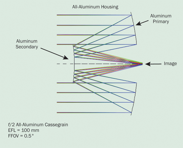
Figure 1. All-aluminum Cassegrain telescope.
The change in the effective focal length (EFL) of the resultant mirror system is scaled by the linear coefficient of thermal expansion. Yet the Cassegrain is still considered to be passively athermal because the image plane remains in focus at varying temperatures. The ray fan plots in Figure 2 illustrate that the optical system remains focused.
The mirror parameters that changed are the radii of curvature, separation of the mirrors and the refractive index of the air. Assuming the index variation of air with temperature is small for these applications, the discussion will be limited to the other parameters.
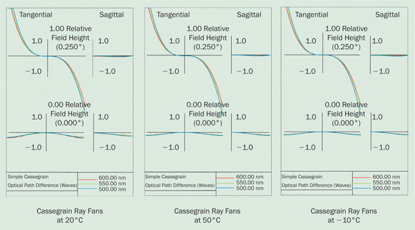
Figure 2. Ray fans for a simple Cassegrain.
In this example, the expansion coefficients of the primary and the secondary are identical to the housing material. Therefore, the optical system remains in focus throughout the temperature range of –10 °C to +50 °C. For instance, as the temperature increases, the power of the primary and secondary mirrors gets weaker. The image remains in focus because the housing material expands proportionally with the change of power in the mirrors. This is the simplest manner to passively athermalize an optical system for any temperature variation.
If this example used different materials for the primary, secondary and housing, the athermalization problem would become more complex, but the basic principles would remain the same. The primary power would change at a different rate than the secondary power, and the housing material would have to be chosen such that the image remained in focus. Reflecting systems that are passively athermalized in this manner are more likely to experience other aberrations in addition to defocus when used at extreme temperatures.
In some applications, the nominal off-axis performance of a catoptric system is insufficient, in which case the catadioptric system may be employed.
Catadioptric systems
Catadioptric lenses are hybrid optical systems that use both reflective and refractive elements in the optical design to achieve the desired performance. These systems offer the advantage of improved off-axis optical performance by reducing field aberrations. For the sake of discussion, the Cassegrain design shown in the first section will be modified by inserting a doublet near the image plane and then reoptimizing the surfaces for peak performance. The resultant design is shown in Figure 3.
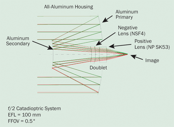
Figure 3. Catadioptric optical system.
The power distribution of the optical elements in the catadioptric system is similar to a Cooke triplet with the primary mirror as the positive element, the secondary mirror as the negative element and the rear doublet as the positive corrector. The rear doublet consists of a negative flint lens (NSF4) and a positive crown (NP SK53) lens. The marginal ray height on the rear doublet is small due to the proximity to the image plane. Consequently, the doublet has a lesser impact on focus over temperature than the mirrors, but it cannot be ignored.
As in the previous example, the primary and secondary mirrors are made of the same material as the housing. However, the additional complication for the catadioptric system is the impact of the refracting doublet over temperature. The TCR (dn/dT) and the CTE of each lens material pose an additional complication to the passive athermalization issue. Table 2 shows the temperature coefficient of refraction (dn/dT) and the coefficient of thermal expansion for each element.
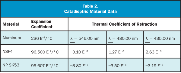
The change in the EFL of the resultant mirror system and doublet system is modified by both the CTE and TCR (dn/dT). Yet the Cassegrain is still considered to be passively athermalized because the image plane remains in focus at higher and lower temperatures. The ray fan plots in Figure 4 illustrate that the optical system remains focused. The plots are at room temperature and 50 °C. The plot at –10 °C is nearly identical to the 50 °C plot.
The coefficient of thermal expansion impacts the radii of the doublet lenses in a fashion similar to that illustrated by the catoptric example (i.e., the radii become weaker as the temperature increases). However, the CTE of each doublet material is less than half of the aluminum expansion coefficient used for the housing. Therefore, the TCR of each lens must be carefully chosen to compensate for the different thermal expansion coefficients if the optical system is to remain in focus.
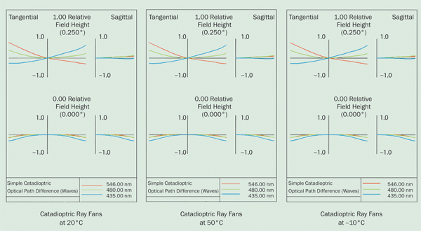
Figure 4. Ray fans for a catadioptric system.
In this example, the TCR for the negative lens is positive, causing the lens to grow more negative as the temperature increases. Likewise, the positive lens has a negative TCR, which makes the lens less positive as the temperature increases. The overall effect is to cause the power of the rear doublet to become weaker as the temperature increases and thereby compensate for the effects of the expanding aluminum housing.
Refractive afocals
The Galilean telescope is an afocal arrangement of positive and negative lenses that can be used to expand beams or change fields of view. The last example for examination is a Galilean telescope consisting of two lenses used in the mid-wave infrared portion of the spectrum. The equation that describes this optical system is given below. Note that Equation 2, below, is very similar to Equation 1:
φL1 + φL2 – φL1 φL2 D = φAFO = 0
Where
φL1 = power of lens 1 (the front element)
φL2 = power of lens 2 (the back element)
D = distance between the principal planes of the elements
φAFO = power of the afocal system, which by definition is zero
Optical systems of this type are considered passively athermalized if energy exiting the last lens remains collimated over the operating temperature range. In some more demanding applications, a further constraint restricting the magnification change over the temperature range may be specified.
The magnification of these systems is given by:

Figure 5 is an example of a Galilean telescope operating from 3.0 to 5.0.
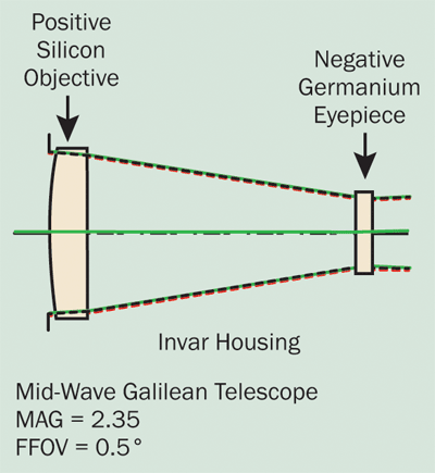
Figure 5. Galilean refracting telescope.
The change in collimation of the exiting beam of the refracting afocal system is modified by both the CTE and TCR for the optical materials and the housing. The thermal coefficients for these materials are shown in Table 3.
For this example, the paraxial change in collimation is about 18 μrad (well within the diffraction limit). The change in collimation as traced by the ray fans is within the quarter-wave Rayleigh criteria, as shown below. As in the catadioptric example, the ray fans at –10 °C and 50 °C are shown in Figure 6.
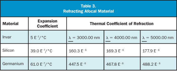
The housing material selected for this example is invar (a nickel-iron alloy). This material has a very low expansion coefficient compared with aluminum or other metals. The positive objective lens is spherical and is made of silicon. It has a small coefficient of expansion and a moderately large positive thermal coefficient of refraction. This indicates that the lens would get more positive as the temperature increases. Similarly, the negative germanium lens of the eyepiece also has a small expansion coefficient and a large positive thermal coefficient of refraction. This indicates that the eyepiece lens becomes more negative as the temperature increases. Therefore, when these lenses are used in an afocal configuration and mounted in invar, their dimensional and material changes offset each other such that the exiting beam remains collimated. Additionally, the change in magnification is only about 0.3 percent.
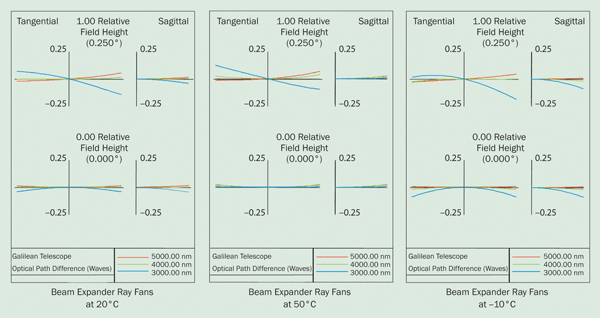
Figure 6. Beam expander ray fans.
The examples in this article illustrate that passive athermalization can be achieved in reflective systems, hybrid systems and refractive systems. Additionally, passive athermalization can be achieved by choosing the housing material to be identical to the optical material, choosing the optical component properties to compensate for the housing material and choosing the housing material to compensate for the optical properties of the components.