Economic and performance issues are the impetus behind the OEM switch from building in-house to optomechanical vendors.
Mark Anderson, Alpine Research Optics
One area of the optics industry that continues to experience growth is that of precision optomechanical assemblies. This trend runs in parallel with increased reliance on more sophisticated laser-based instrumentation, which places extreme demands on the performance of both optics and mounts. As a result, end users may find it more economical to purchase integrated optomechanical modules rather than building them in-house.
Ideally, the optomechanical module can be assembled into the OEM’s own equipment through the use of precision registration to one or more mounting surfaces or mechanical interfaces. This eliminates a company’s need to maintain significant optical design, assembly and testing capabilities in-house. For example, measuring wavefront might require a 6-in. Fizeau interferometer with a phase-shift option, which not only can cost as much as $100,000, but also require a trained technician to perform the testing.
It also is possible to eliminate the cost associated with overspecified components as well as the tendency for inexperienced engineers to design assemblies that are difficult or expensive to manufacture. In both cases, outsourcing assembly manufacture can reduce costs. Success requires close communication between the contractor and the OEM customer to clearly define the expected input and output of the assembly, including all critical specifications and tolerances.
Inventory costs also can be reduced with the use of lean manufacturing and assembly principles and the introduction of a kanban system to pull parts through the process on demand. Combined with close cooperation with the optomechanical vendor, this can improve build-to-order times for the end product. Communication must be characterized by good, flexible supply agreements, including accurate forecasts.
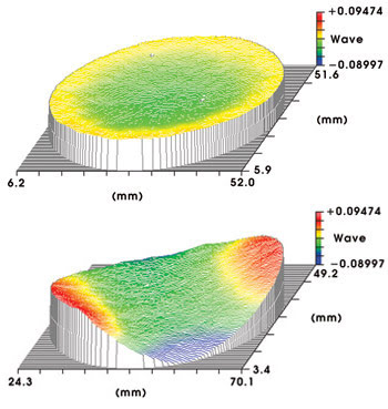
Performance issues are less of a problem as well. Because the performance of components such as low-wavefront or high-flatness optics depends in large measure on how they are mounted, the responsibility for achieving specified goals shifts to the supplier (Figure 1).

Figure 1. Mounting issues can generate significant problems in conventional optomechanical assemblies. These interferometrically measured surface figures include an unmounted mirror showing λ/20 native surface distortion (a), and the same part when supported by a commercial three-point mirror mount employing plastic interface contacts and moderate clamping force (b). The latter case shows that flatness has deteriorated by a factor of 4×.
Redesigning for lower cost
Unnecessary complexity is a common problem in optomechanical system designs. This is manifested in designs with redundant or unnecessary degrees of freedom, as well as in systems that contain too many parts. These issues can increase system cost, complicate alignment and lower long-term stability. For example, when kinematic mirror mounts are bolted to brackets that separately bolt to chassis features, the alignment tolerances of the brackets themselves introduce an additional assembly variable and may lead to thermal and mechanical stability problems.
A fiber-coupling system that is used in an illumination tool for ophthalmic surgery serves as another example. The purpose of this optomechanical subsystem is to collect the light from a filament lamp and to collimate, filter and focus it into a fiber bundle. The assembly includes a spare lamp and backup optical train in case of lamp failure during a surgical procedure.
The original design, executed internally by OEM scientists, produced an expensive subassembly. An analysis performed by the author revealed some inherent problems with the design, which consisted of multiple mounts and brackets bolted together. In particular, a critical right-angle mounting bracket had too much flexibility, making it difficult to machine and still guarantee that the perpendicularity requirements stated on the prints could be met.
The solution was to machine the subassembly from a single aluminum block. The only bolt-on parts were filter holders constructed of sheet metal — parts whose precise location and alignment were not critical. This arrangement reduced the fabrication and testing costs by better than 30 percent, while eliminating more than 50 percent of the custom-machined components. Moreover, the more efficient thermal and structural design improved coupling efficiency and optical stability. At the same time, assembly reproducibility was improved because of the elimination of unnecessary components and interfaces, each of which had contributed to the overall mounting tolerances of the critical optical components.
This example illustrates an important concept in optomechanical design. Combining modern CAD/CAM mechanical design and computer numerical control machining means that mechanical parts with complex shapes can often be machined for considerably lower cost than it takes to produce an assembly with several simple parts. This provides the added benefit of improved long-term stability.
This trend is becoming very common among laser manufacturers, as improved lifetimes for diodes, doubling crystals and other active components cause optical drift to be a limiting factor in “hands free” performance. In such cases, optical mount designs that minimize the number of components can resolve problems.
Testing unique assemblies
Some issues arise from testing optomechanical performance. With loose optics, it is relatively straightforward for a vendor and customer to agree on a set of performance specifications that can be objectively verified by standard testing methods. But optomechanical designs typically involve not only complex alignment requirements, but also the traditional surface quality and wavefront specifications. For example, the customer might request the relative alignment of the optical axis with a reference mounting surface or set of mounting holes.
Nonstandard specifications naturally involve unusual testing and verification methods. One example of this involves a mounted mirror assembly used in a precision laser-based surgical tool. In this case, the optic had to be mounted to produce less than three arc minutes of deviation between the final optical axis and the target axis. This complicated both assembly manufacture and inspection.
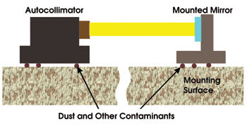
Engineers verified alignment with an autocollimator-based method, but at this level of accuracy, measurements are affected by dust or other contaminants trapped on the mounting surface (Figure 2). To avoid disputes with customers concerning true performance, this process required an objective measurement system and protocol. It also had to deliver unambiguous results without technician intervention.

Figure 2. Checking optomechanical alignment with an autocollimator requires precise registration of the autocollimator and the optic(s). With high-precision alignment, even dust trapped on the mounting surfaces can lead to microscopic alignment errors.
The solution was to develop custom tooling to hold both the autocollimator and the part under test in a stable, repeatable manner. Once engineers verified the accuracy, stability and reliability of this tooling, two identical sets were created. The vendor kept one and gave the other to the customer. The use of an improved testing method enabled the customer to manufacture a more consistent product, and the use of identical tooling by the vendor eliminated returns and controversy over specifications.
Designing for reliability
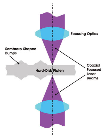
The final example involves a laser-based system used to texture the flying head “landing area” on a computer hard disk. This requires focusing a pulsed laser beam onto both surfaces of a hard disk simultaneously, with both beams precisely aligned to produce an exact registration of the bump pattern on the upper and lower surfaces of the disk (Figure 3).

Figure 3. The optomechanical assembly used for laser texturing of hard disks must be precisely aligned so that the laser beams are collinear at the disk.
The original tooling generated by contractors to the OEM incorporated numerous optical elements, including lenses, mirrors and wave plates. A complex set of mounts was necessary to make adjustments to co-align the focused beams. The resulting optomechanical assembly could not withstand the rigors of the production line and would frequently drift out of alignment, causing a shutdown on the line. And, despite its complexity, it did not deliver all the necessary optical adjustments, so that in some instances the whole tool, which weighed approximately 50 pounds, had to be moved relative to the laser beam to produce the desired alignment.
In this case, the redesign goal was to produce a system with the requisite stability and reliability. Manufacturing and testing costs were secondary. This was a direct result of the economics of the disk production process. Specifically, laser disk texturing is economical only when working at high throughput. As a result, the cost of downtime far outweighs the cost of the machinery used.
The redesigned system was simpler, yet still managed to provide all of the appropriate degrees of freedom for alignment in the manufacturing setting. The need to move the entire assembly to achieve alignment was eliminated by the use of appropriately placed mirrors. Special care was taken to develop optical mounts that wouldn’t create distortion or drift.
Several methods were developed to guarantee alignment. For example, one requirement was that the top and bottom beams be perfectly collinear. To accomplish this, the system was set up without the hard-disk target. Only the top beam was powered up, and it was made to trace a path back through the bottom optics to the beams’ source. Because the system thus aligned itself, collinearity was ensured.
Moving on up
In each case discussed, optimizing the product involved outsourcing the assembly design and production. Projects of this nature require the services of an optomechanical company more than an independent optics manufacturer or mechanical machine shop. By transforming themselves into optomechanical companies, optics manufacturers can move up on the value chain and develop closer relationships with customers. And making the technology easier to implement can serve to broaden the market for photonic solutions.
About the author
Mark Anderson is engineering manager at Alpine Research Optics in Boulder, Colo.; e-mail: [email protected].