Sophisticated testing instruments, as well as integrated calibration and error correction software (or stand-alone software systems), can evaluate today’s complex designs. Such tools position designers to successfully tackle challenges in the even faster data environment of the future.
CHRIS LOBERG, TEKTRONIX INC.
The demand for optical network data has soared, with rates of 100 Gb/s evolving into 400 Gb/s, 1 Tb/s and beyond, pushing designers to explore inventive and even unconventional modulation schemes in order to encode data more efficiently for faster throughput. In this context, it can pay off for designers to think about how to optimize their testing environment to quickly and accurately evaluate design progress.
When considering a coherent optical modulation analysis system, it’s important to consider the signal fidelity of its acquisition system. This typically includes an optical modulation analyzer (OMA) or coherent receiver, as well as a digitizer (usually an oscilloscope), and some form of algorithmic processing.
When purchasing a coherent optical acquisition system, users must look beyond obvious performance parameters, such as coherent receiver bandwidth and oscilloscope sample rate. Consider also these vital questions:
• Does this OMA achieve the lowest possible error vector magnitude (EVM) value for the acquisition system? And is this oscilloscope the most effective digitizer available? These two considerations have an obvious impact on measured signal quality.
• Is the analysis software that comes with the OMA adequate for testing the complexities of the design or research?
• Do these instruments meet not only present acquisition needs, but also anticipated needs in one year, two years or even longer?
Achieving low EVM and high ENOB
Signal quality is obviously critical to testing success. EVM is often seen as a representation of the overall signal quality — the lower the better. An EVM is simply the vector that points from the actual measured symbol to where that symbol was intended in the signal constellation diagram.
The manufacturing process can introduce a wide range of system impairment and configuration issues into the OMA, which can adversely impact the receiver EVM. These include IQ (in-phase and quadrature) phase angle errors, IQ gain imbalance, IQ skew errors, and XY polarization skew errors. The good news is that some OMAs are able to precisely measure these manufacturing errors and calibrate their impacts in the algorithmic processing that typically follows coherent detection.
With these OMAs, each receiver is tested at the time of manufacture, and a unique calibration file is created. It is later automatically used by the optical modulation analyzer software that comes with the receiver to remove the impacts discussed above during acquisition.
Figure 1 offers an example of the software that accompanies a Tektronix OM4245 45-GHz OMA. Unique calibration files are created for all Tektronix OMAs at the time of manufacture, so that the software can remove any impacts. Once the signal is received by the OMA, the next step is to digitize it on the electrical signal paths using a multichannel oscilloscope. This can introduce a number of factors that can affect the EVM, the most fundamental being the oscilloscope’s bandwidth and sample rate.
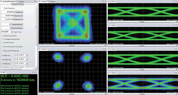
Figure 1. An example of the software that accompanies optical modulation analyzer (OMA) systems; here, a Tektronix OM4245 45-GHz OMA is shown.
Assuming an oscilloscope with the appropriate bandwidth and sample rate is utilized, and that all OMA impairments are being corrected algorithmically as described above, achieving the lowest measurable EVM comes down to a function of the effective number of bits (ENOB) of the oscilloscope. The ENOB is measurably impacted by the way the oscilloscope handles interleaved sampling. Some real-time oscilloscopes use frequency interleaving techniques in order to extend bandwidth, but they do so at the cost of increasing the noise in the measurement channel.
The limitation of the frequency interleaving approach lies in how the various frequency ranges are added together to reconstruct the final waveform, a step that compromises noise performance. In traditional frequency interleaving, each analog-to-digital converter (ADC) in the signal acquisition system only “sees” part of the input spectrum. But other oscilloscopes, such as the one shown in Figure 2, use a time-based interleaving approach, where all the ADCs see the full spectrum with full signal path symmetry. This approach preserves signal fidelity and ensures the highest possible ENOB.
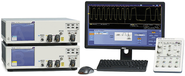
Figure 2. Some oscilloscopes, such as this one, provide signal acquisition up to 70-GHz bandwidth. Its asynchronous time interleaving (ATI) architecture provides a low-noise, real-time signal acquisition and high effective number of bits (ENOB).
Analysis for conclusive evaluationAny test and measurement coherent receiver comes with some sort of analysis and visualization software package. But will that software have the particular types of measurement and visualization tools needed for evaluating specific designs or research?
For example, when evaluating the quality of a new phase recovery algorithm, OMA software may be needed. This type of software can provide not only the basic building blocks for measurements but also allows the complete customization of the signal processing. Stand-alone optical analysis software packages of high quality are on the market. Some include features such as a library of analysis algorithms designed specifically for coherent optical analysis and executed in a customer-supplied MATLAB installation, with an applications programmatic interface (API) to these algorithms. Some provide a graphical user interface with optical tools that analyze complex modulated optical signals without needing to know any MATLAB, analysis algorithms or software programming, as shown in Figure 3.
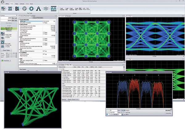
Figure 3. The user interface of software like this, Tektronix’s OM1106 Coherent Optical Analysis system, allows the user to conduct a detailed analysis of complex modulated optical signals without requiring knowledge of MATLAB, analysis algorithms or software programming.
Flexible measurement-taking software also is available. For instance, measurements can be made solely through the user interface, or via the programmatic interface to and from MATLAB for customized processing. Using both methods together is also an option, made possible by employing the user interface as a visualization and measurement framework, around which custom processing can be built.
Most software includes sophisticated core processing algorithms for analyzing coherent signals — estimating the signal phase, determining the signal clock frequency, performing ambiguity resolution, estimating the power spectral density, etc. — but some packages can customize the core processing algorithms. This provides an excellent method for conducting signal processing research. For instance, in order to speed up the development of signal processing routines, one user interface provides a dynamic MATLAB integration window (Figure 4).
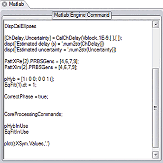
Figure 4. A dynamic MATLAB integration window helps speed up the development of signal processing routines.
Any MATLAB code typed in this window is executed on every pass through the signal processing loop. This allows the “comment out” function calls, writing of specific values into data structures, or modification of signal processing parameters on the fly without having to stop the processing loop or modify the MATLAB source code.
Future-proofing an acquisition system
While the bulk of today’s coherent optical R&D activity is focused on 100-G signals, R&D with 400-G signals is already underway at many sites. Testing at 400 G may well be needed within the lifetime of many 100-G test instruments. Therefore, it makes sense to buy equipment at the right performance and price for 100 G now, but also to ensure that future expansion into 400 G is possible.
But how? Typically, four channels of 33-GHz real-time oscilloscope acquisition are used to test 100-G signals. In order to test 400-G signals in the future, bandwidths greater than 65 GHz will be needed, especially for a full dual-polarization system. But if testing at 100 G is all that’s needed now, it could be hard to justify the additional expense. One way around this problem is to purchase a system with a flexible, modular design, and one that uses distributed processing to allow for additional capacity for the system as needed.
For example, Figure 5 shows a system with four channels of 33-GHz acquisition that are distributed across two stand-alone oscilloscopes (left). The instruments are connected by a high speed bus, which not only provides a common external trigger between the two but also includes a common 12.5-GHz sample clock. The result is that the two oscilloscopes are combined to form, in effect, a single instrument whose acquisition-to-acquisition jitter across all channels delivers the same level of measurement precision as a stand-alone, monolithic oscilloscope.
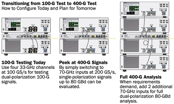
Figure 5. Shown here is a modular way to build coherent optical testing systems from 100 to 400 G using an oscilloscope connected by cables. The processing is distributed and provides a common trigger without acquisition-to-acquisition jitter.
The system shown in Figure 5 also has two 70-GHz channels (one in each unit). Therefore, by simply switching from the 33-GHz channels to the 70-GHz channels, the oscilloscope bandwidth and sample rate can both be doubled. This permits a “peek” at single-polarization 400-G signals using the 100-G test system, as shown in the middle of the illustration. When the time comes to perform full 400-G testing, a second system can be added to the first with another high speed bus, providing two more channels of 70-GHz acquisition. This creates a system that is capable of full dual-polarization coherent optical acquisition (as demonstrated on the right).
As the base units are stand-alone oscilloscopes, the systems can also be scaled down and redeployed to other projects as needed when a project comes to an end.
Meet the author
Chris Loberg is a senior technical marketing manager at Tektronix Inc., responsible for oscilloscopes in the Americas region; email: [email protected].