High speed, a wide measurement area, a large vertical range and subnanometer vertical resolution are key benefits of this inspection technique.
Mike Zecchino, Erik Novak and Joanna Schmit, Veeco Instruments Inc.
Optical profiling (white-light interferometry) is a noncontact technique for determining surface texture and shape, from nanometer-scale roughness through millimeter-scale step heights. The strengths of this method— high speed, a wide measurement area, a large vertical range and subnanometer vertical resolution — lend themselves to a variety of metrology applications in research, product and process development, in manufacturing and in quality control.
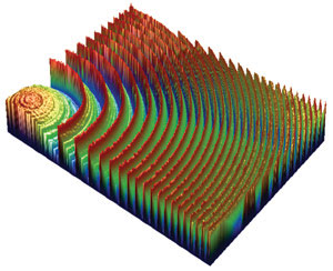
Figure 1. A Fresnel lens, imaged using enhanced vertical-scanning interferometry, exhibits an essentially smooth surface but with regular discontinuities too tall for phase-shifting interferometric measurement. Courtesy of Glimmerglass.
A standard optical profiler arrangement includes an illumination source, traditionally a tungsten-halogen bulb, coupled to an optical system with a variety of interferometric microscope objectives (Figure 2). The choice of objective depends upon the test surface and the size of the features of interest. The illumination splits within the objective, with part of the beam going to the test surface and part to a high-quality reference surface. The two beams recombine to form a pattern of interference fringes, the intensity of which is recorded by a CCD camera (Figure 3).
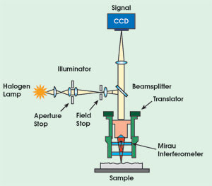
Figure 2. A white-light optical profiler measures surface features from nanometer-scale roughness to millimeter-scale steps.
With the reference surface translated relative to the test surface, every point on the surface passes through focus. Throughout the scan, the system records a series of intensity data frames and analyzes them using various techniques to determine the height of each point.
The two techniques traditionally used to determine surface heights from the recorded intensity data are phase-shifting and vertical-scanning interferometry. The former relies on detection of the phase of the fringes to produce topographic data with very low noise and subnanometer vertical resolution, but is limited to surfaces with discontinuities typically less than 160 nm. The latter, also known as white-light or coherence-sensing interferometry, works by detecting the peak contrast of the fringes. It thus avoids the height and slope limitations of phase-shifting interferometric techniques and can measure steps to 8 mm, but there may be some sacrifice in accuracy and noise rejection.
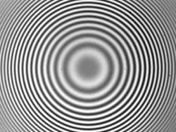
Figure 3. A CCD camera measures the intensity of interference fringes generated by optical profiling systems on a variety of complex surfaces.
An optical profiler can measure a relatively large surface area (approximately 50 sq mm) in a single scan, enabling dramatically faster measurement speed than raster-scanning techniques such as stylus profilometry or confocal microscopy. Stitching algorithms further increase the field of view, making it possible to combine multiple measurements into one large data set. Measurement speed ranges up to 100 μm/s, depending on the desired vertical resolution.
Another benefit of optical profiling is the data analysis capability. Besides measuring standard surface parameters such as average roughness, rms roughness and peak-to-valley height, profilers provide two- and three-dimensional false-color height maps, histograms, bearing ratio, curvature and volume analysis.
The noncontact nature of interferometry also allows measuring surfaces that are soft, adhesive or easily damaged. Capability to measure both smooth and rough surfaces extends the technique to a wide range of applications, including optics, paper, pharmaceutical products, semiconductors, metals and materials, data storage devices, medical components and microelectromechanical systems (MEMS).
Vertical position analysis
One challenge to obtaining accurate interferometric measurements is to precisely track the scanner’s vertical position at all points during a scan. In a traditional optical profiler, both the scanner speed and the mean wavelength of the detected fringes affect the measurement quality. Often, though, measurement of one requires the assumption that the value of the other is well-known and constant. Traceable step standards can then be used to calibrate the system.
Unfortunately, these assumptions do not always hold true. Variables such as nonlinear scanner motion, fluctuating temperature and other environmental conditions, as well as inherent uncertainty of the standard itself, all influence the interpretation of vertical position. Over a short scan range, these variables are typically acceptable, and calibration to certified standards is adequate. When the vertical scan length reaches several millimeters (as is often required for measuring features of MEMS and photoresists), or when feature dimensions are on the submicron scale, the potential variability becomes significant.
Another method for tracking scanner position adds a distance-measuring interferometer to the primary measurement system. Acting as a reference signal, this uses a separate, narrow-band laser source with a well-controlled mean wavelength (632.8 nm) that shares the same focusing mechanism as the scanner (Figure 4). The reference signal is acquired by photodiode detectors and is routed to the computer for processing.
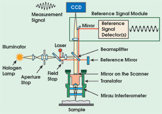
Figure 4. Adding a reference signal to an optical profiler allows calibrating the phase and wavelength of the fringes during each measurement run. The wavelength of the reference signal supplies a traceable, primary length standard.
During measurement, the inspection system acquires sample and reference signals simultaneously because the scan rate is the same for both. The comparison and synchronization of both signals is based on the time stamp associated with each data sample. The reference signal allows characterizing the scanner error position (speed). Rather than correcting the scanner motion, the measurement algorithm uses the information about the scanner position to directly compensate for variability. This substantially reduces the influence of scanner errors, lowering the noise floor and providing more accurate height profiles.
The reference signal enables the system to calibrate the period of the fringes during each measurement run and to provide the mean effective wavelength that is registered by the camera. The wavelength of the reference signal supplies a traceable, primary length standard with which the measurement algorithms compare all data. Thus, the system is continuously calibrated for each measurement run.
This arrangement eliminates the uncertainties of calibrating with a step-height standard and obviates the need for frequent recalibration as well as the potential for drift between calibrations. For research labs, this ensures measurement accuracy that is independent of the operator or environment.
For manufacturers running several profilers in a production environment, it represents a significant reduction in instrument maintenance as well as ensuring tool-to-tool correlation over time.
New measurement mode
Another new technique, called enhanced vertical-scanning interferometry, combines the resolution of a phase-shifting interferometric measurement over a vertical scan range in the realm of vertical-scanning interferometry. The algorithm used with this method first determines the coarse height using a vertical-scanning interferometric technique. It then determines the phase data about this point. By combining these two sets of information, and by employing the reference signal for vertical positioning, the height of each point can be determined with subnanometer resolution over the larger scan range.
The method also extends optical profiling to difficult-to-measure samples, such as those with large discontinuities or with peak-to-valley heights that exceed the system’s depth of field.
End users can obtain surface profiles with high resolution from diverse sources, from binary optics, gratings and MEMS devices to a Fresnel lens where the surface is essentially smooth but has regular discontinuities that are too tall for phase-shifting interferometry.
The reference signal, self-calibration and enhanced vertical-scanning interferometric measurement mode are all commercially available, as they are in Veeco’s Wyko NT8000 model.
To date, optical profiling has been employed for measuring the surfaces of static samples only. Static measurement has been useful for verifying and controlling MEMS etch and deposition processes, yet it has not been able to fully characterize how a device will react under actual working conditions. The commercialization of MEMS devices has therefore created a growing need for characterizing microdevices in motion, as they actuate.
The main obstacle to measuring moving devices is that vibrating structures can obscure or distort the interference fringe pattern, even at low frequencies and amplitudes. But, if device motion is periodic, as with most MEMS structures, one can strobe the illumination source in synchronization with the MEMS drive signal to effectively freeze the motion. One can then use standard optical profiler techniques to characterize the surface. Multiple measurements can be taken as the amplitude, phase and/or frequency of the drive signal are varied, allowing description of the device’s full range of actuation/deformation.
Dynamic measurement
In a dynamic measurement profiler, an additional LED source provides the strobed illumination (the halogen source is retained for static measurements). Employing a strobed LED source requires careful hardware and software design to maximize its efficiency while prolonging its life. Such techniques have been used on a Wyko NT1100 optical profiler and shown to produce effective results.
The primary benefits of optical profiling — noncontact measurement, high speed and high resolution —carry over from static to dynamic measurement. Each measurement at a particular voltage, phase or frequency requires only a few seconds, allowing full characterization of the device in a short time. The series of data image frames also can be recombined to generate a video of the device in motion (Figure 5).
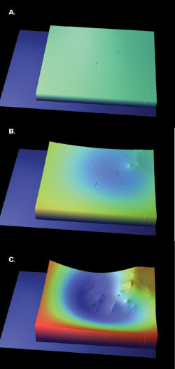
Figure 5. At rest, a micromirror appears flawless (top). By actuating the mirror and examining several frames taken from a dynamic measurement of that surface, optical profiling reveals a hidden defect. Courtesy of Texas Tech University.
Besides simple visualization, the dynamic profiler allows 3-D measurement of critical dimensions and deformation across the range of actuation, for both in-plane and out-of-plane motion. Template-driven software analysis helps isolate and track features of interest across the multiple frames of data.
Once the features are identified and tracked through the data, end users can derive key device parameters, such as linearity and range of motion, shape/distortion, radius of curvature and sag/bow. These parameters provide the basis for software calculation of resonant frequency, modal behavior, and settling and switching times.
Optical profiling is a mainstay technology for researchers and manufacturers in diverse applications. The combination of speed, range and resolution has allowed profilers to characterize the pitting on space vehicle skins, electrostatic damage to food packaging, wear on metal parts and hundreds of other applications.
Recent developments have extended this utility by improving measurement accuracy and range and by adding the ability to measure both static and moving parts. Other advances under development will continue to increase this range of utility well into the future.
Meet the authors
Erik Novak is director of R&D for optical products, Joanna Schmit is a senior optical engineer and Mike Zecchino is the technologies writer for Veeco Instruments Inc. in Tucson, Ariz.