A 3D-printed brain model equipped with optical fibers aims to help clinicians and patients visualize brain function activity, overcoming the shortcomings of four-dimensional neuroimaging techniques.
THOMAS BRITTON, RARITAN VALLEY COMMUNITY COLLEGE, and JAEHAN KIM, OFS FITEL LLC
Medical imaging faces inherent limitations depending on its presentation mode. Computer models and virtual reality, while much more effective than two-dimensional depictions, are nonetheless images on a computer screen. Even with the use of stereoscopic techniques, the ability to visualize may depend on the use of a keyboard or mouse to interpret the model. In the case of 4D experimental medical data — such as electrophysiological, MRI and others — objects are displayed as computer animations or static pictures. While there are techniques that can make it easier to understand 4D data, virtual models do not offer the same native interaction or spatial information as a physical object.

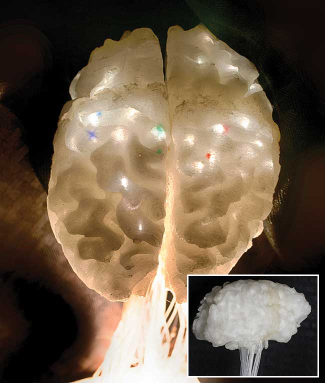
Figure 1. Example images of the illuminated illustrative brain model. A
neuroimaging cortical flat map is projected onto an optical fiber
bundle in the model brain stem and the light is piped to the appropriate
brain active-regions as indicated by the bright regions in the images.
Illuminated brain model
Alternatively, a hands-on, 3D-printed brain model can allow the user to fully observe the appropriate anatomical features of the subject brain as captured in 3D neuroimaging. By using colored light, emitted at the appropriate location within the brain structure, one can visualize the display of 4D data.
A proof-of-concept, 3D-printed brain model and illumination device was developed for the visualization of datasets on cortical gray matter. This concept device uses a computer/multimedia projector as the light source to project a neuroimaging cortical flat map1 onto a bundle of optical fibers that is routed to the appropriate active brain centers to illuminate the brain model (Figure 1). A patient-specific, 3D-printed anatomical model has multiple potential uses in education, simulation and prosthetics2, and in communicating and interpreting results between researchers. These models are helpful tools in neurosurgery planning and patient education3. An accurate data display, using light, could enhance the use of brain models by showing the viewer from where, for instance, an EEG seizure focus is coming.

Figure 2. The multi-step process for creating a 3D model file prepared for 3D printing.
An MRI image file and open source software were used to create a 3D computer-model file of the brain model (Figure 2). Several open-source programs, including 3D Slicer4, InVesalius5 and Seg3D6, can convert DICOM (digital imaging and communications in medicine) images into 3D-image volumes. DICOM is a standard for handling, storing, printing and transmitting medical imaging information. Most DICOM viewing and conversion software can convert each image series into a 3D volume and then save the volume as a nearly raw raster data (*.nrrd) file.
The software programs 3D Slicer, InVesalius and Seg3D included segmentation tools that allowed the user to differentiate and label different tissues. In MRI imaging, these tissues are mainly background, cerebrospinal fluid, gray matter and white matter. Using thresholding to label each tissue resulted in label maps, which were used to calculate an isosurface that 3D Slicer can save to a file such as *.vtk, *.obj, *.ply and also *.stl, the most compatible 3D-printing format.
As opposed to openly accessible, presurgical isovoxel scans, the diagnostic scans used were mostly of limited spatial resolution volumes of 30 or fewer evenly spaced image slices. Because of the limited spatial resolution, several scans were coregistered on different imaging planes to a 155-slice axial volume and then combined using arithmetic operations. Thresholding tools were used to label the resulting volume, which yielded a better isosurface model.

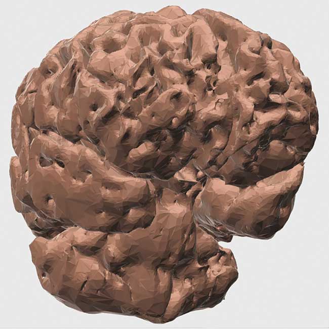
Figure 3. The 3D computer brain model used to make the 3D-printed illuminated brain model. The left anterior quarter is not shown.
The surface models created by the medical imaging software may not be
immediately compatible for 3D printing. Freely available 3D modeling
programs have the tools needed to repair and allow the models to be
sliced (converted into a toolpath) for 3D printing (Figure 3).
The software tools Meshmixer and Netfabb Basic were used to repair any issues with the model. Several tools in the programs were used to optimize the model as well, including polygon reduction, plane cutting, transformations, hollowing, overhang analysis and support material generation, along with others. The hollowing tool in Meshmixer was used to hollow the 3D computer brain model to 2.5 mm.
3D printing
Fused filament 3D printing was used to make the brain model with a basic kit built using an open-hardware, 3D printer (OneUp by Quintessential Universal Building Device Inc.) including Arduino and RAMPS 1.4 controller boards. The printer and open-source software package, including Repetier Host and Slic3r, recommended by the printer’s makers, was very versatile down to the toolpath level.
The brain model was printed in four separate parts, roughly quartered at the mid-sagittal and mid-coronal planes. The model was also cut in the axial plane below the temporal lobe. The region below the cut, including some of the brain stem and cerebellum, was removed. The model quarters were scaled down to 70 percent of the original size to fit the quarters in the printer’s build area, and then hollowed to a wall thickness of 3 mm, and printed with Meshmixer-generated “tree” supports. The model was printed with the coronal plane cut down on the build plate. This approach was needed because the overall round/oblong shape of the human brain, especially with the Sylvian fissure and the hollowing of the model, would have required more supports and included a chance of error if oriented in any other way.
The physical 3D brain model, once hollowed, had large openings in the pons and brain stem region. The brain stem opening was measured and an online calculator was used to determine the number of fibers that could be introduced. Routing holes were drilled through the brain model, and a fiber was inserted through each hole from the outside and through the model to exit from the cavernous openings at the brain stem. The fibers were indexed by lobe along with the brain landmarks of the corpus callosum, hippocampus and central sulcus. Then neighboring fibers were bundled together.
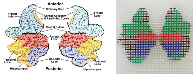
A plastic grid was used to achieve a breakout of the bundle in the pattern of a “cortical flat map,” which represents neural activity of the brain as a 2D colored map (Figure 4). This grid was the target of the projected image of an actual cortical flat map. Each optical fiber was indexed and inserted through its respective hole in the flat-map grid, glued into place and then cleaved. Once the fiber bundles were glued into the brain stem openings, the front and rear quarters of the hemispheres were glued together. The fibers were cleaved at the model’s surface, pushed through their respective holes and the holes were then sealed.

Figure 4. The cortical flat map (a) and plastic grid (b) are used to achieve a breakout of the bundle in the pattern of a cortical flat map.
The medical imaging computers unfolded the brain geometry to portray the 4D brain activity on cortical flat maps. This optical fiber bundle and grid arrangement then folded the flat-map data back up and projected it into the 3D brain model.
Illuminating the brain with optical fibers
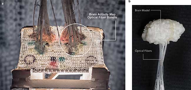
A small portable digital projector was used to illuminate the brain model, while a tower support structure held the brain model, optical fiber brain stem and cortical flat map grid in place with an inline focusing lens in between. The illumination device tower was designed to rest on top of the projector. A test pattern animation was used to test the gross validity of the flat map image illumination. The grid and fiber interface were covered with black modeling material to block excess light from contaminating the brain model. In addition, the optical fiber bundle and supporting frame (Figure 5) were covered with an opaque paper to prevent light leakage.

Figure 5. A small portable digital movie projector was used to illuminate the brain model through the fiber bundles indexed into the grid (a). A support structure holds the brain model and fibers/grid in place, in line with a focusing lens placed in between (b). Black paper enclosing the support frame is not shown here.
A 3D-printed brain model with optical fiber illumination can be used to display 4D neuroscientific brain data from cortical flat maps. The brain model displayed the test pattern correctly (Figures 1 and 5); the optical fiber lit the model from the inside, colors were distinguishable in a darkened room and the fibers fed light to areas on the brain model consistent with the cortical flat map. Used “as is,” the device will depict brain activity data at approximately the resolution of a scalp EEG. An educational model on brain function can be developed based on this device.
Meet the authors
Thomas Britton is an engineering student at Raritan Valley Community College in Branchburg, N.J. He is interested in developing improved methods of displaying medical neuroimaging data to aid medical staff and patients; email: [email protected].
Jaehan Kim serves as medical market manager for OFS, based at the company’s facility in Avon, Conn.; email: [email protected].
Acknowledgment
The authors wish to express their appreciation to Dr. Peter Stupak of Raritan Valley Community College for his encouragement during the development of the illuminated brain model and support in the preparation of this article. The authors also acknowledge the generous support of OFS for providing the optical fiber used in this work.
References
1. P. Avanzini, et al. (2016). Four-dimensional maps of the human somatosensory system. Proc Natl Acad Sci USA, Vol. 113, Issue 13, pp. E1936–E1943.
2. A. Marro, et al (2015). Three-dimensional printing and medical imaging: A review of the methods and applications. Curr Probl Diagn Radiol, Vol. 45, Issue 1, pp. 2–9. doi: 10.1067/j.cpradiol.2015.07.009. Epub 2015 Jul 21.
3. J.S. Naftulin, et al. (2015) Streamlined, inexpensive 3D printing of the brain and skull. PLoS ONE, Vol. 10, Issue 8, p e0136198. doi:10.1371/journal.pone.0136198.
4. A. Fedorov, et al. (November 2012). 3D slicer as an image computing platform for the quantitative imaging Network. Magn Reson Imaging, Vol. 30, Issue 9, pp 1323-1341. PMID: 22770690.
5. T. Moraes, et al. (2011). InVesalius – An open-source imaging application. VIPIMAGE 2011, Algarve, Portugal. Computational Vision and Medical Image Processing, Vol. 1. London: Taylor & Francis Group. pp. 405-408. http://svn.softwarepublico.gov.br/trac/invesalius.
6. Seg3D, www.sci.utah.edu/cibc-software/seg3d.html.
Optical Fibers in OCT, Endoscopy and More
Besides illuminating a 3D-printed brain model, the physical characteristics of high-quality silica optical fiber make it a natural choice for a broad range of real-world uses, including many in the imaging and medical fields.
Since the 1960s, one of the most significant and prevalent applications of fiber optics in medicine has been in the imaging and illumination components of endoscopes. These instruments are used extensively to visualize internal organs and tissue that can be reached through either natural openings or a small transcutaneous incision in the skin.
An endoscope uses optical fibers and power lens systems to provide lighting and visualization of the body’s interior. In general, fiber optic endoscopes use two fiber optic lines. The first, a “light fiber,” carries light from a source into the body cavity, and a second “image fiber” carries the image of the cavity back to the physician’s viewing lens. The image is then transmitted to a computer that interprets and displays the gathered information on a monitor. It is also sometimes possible to perform internal medical operations by using an endoscope instead of traditional surgical methods.
In fact, these fibers have been adopted for use for in vivo optical imaging by way of optical coherence tomography (OCT). Using the principle of interferometry, fiber optic probes or OCT catheters deliver image signals. In this process, OCT measures the phase delay of an injected light beam onto a measured surface. As a result, the cross-sectional internal microstructure of tissues or organs can be “visualized” at high resolution in micron scale. Typical uses of OCT are for real-time imaging of the retina of the eye, vasculature and the gastrointestinal tract.
The main advantages of using optical fibers in OCT are high spatial resolution at the micron level, cost effectiveness and technological flexibility with measurement in either time or frequency domain or via 1D or 2D methods1.
While a broad range of optical fibers are available to serve medical imaging applications, developers are increasingly using and creating numerous medical uses for single-mode and multimode optical fibers because these fibers offer a broad range of optical performances2.
In addition, health care providers are increasingly looking to advanced fiber optic-based instrumentation such as ablation, imaging and sensing applications to enable more efficient patient diagnosis, monitoring and treatment3.
The intrinsic physical characteristics of optical fibers make them extremely attractive for medical applications. Biocompatible optical fibers can be loosely inserted or glued directly into hypodermic needles, guidewires and catheters so that their use can be minimally invasive and highly localized. One of the advantages of using optical fibers for medicine is that fibers are immune to electromagnetic interference. In addition, they are chemically inert, nontoxic and intrinsically safe. Their immunity to electromagnetic and radio frequency signals also makes them ideal for real-time use during diagnostic imaging using MRI, CT, PET or SPECT technologies.
With a global population that is both growing and living longer, optical fiber is likely to play an increasingly important role in medical imaging, sensing and numerous other applications yet to be developed.
References
1. J.M. Pelaprat and B. Wang (July 2012). All-fiber probes hold promise for medical imaging applications. Photonics Spectra, pp. 42-45.
2. J. Kim and J. Loft (2016). Optical fibers bring new medical applications to light. Medical Design Briefs, May 1, 2016. http://www.medicaldesignbriefs.com/component/content/article/mdb/features/24677#.V0XaJphQDtE.facebook.
3. A. Mendez (January 1, 2011). Medical applications of fiber-optics: Optical fiber sees growth as medical sensors. LFW. http://www.laserfocusworld.com/articles/2011/01/medical-applications-of-fiber-optics-optical-fiber-sees-growth-as-medical-sensors.html.