Focusing system extends liquid lens autofocusing for mobile phones.
Olivier Jacques-Sermet, Varioptic SA
Because of the current trend of decreasing pixel size to increase pixel count on CMOS imaging sensors, autofocus is becoming necessary to maximize the use of the sensor in its full-resolution capability over a wide depth of field. Hence, autofocus is being adopted as a standard feature in high-resolution imaging systems, typically those above 2 megapixels. As a result, new autofocus mechanisms are under development, including one using liquid lens technology.
An autofocus lens can focus on different planes from infinity to a distance as close as 10 cm. To produce a sharp image, the lens must focus at the distance where the subject can be located. In applications such as mobile phones, space and cost restrictions prevent the use of a distance sensor. As a result, finding the best focus position requires driving the autofocus actuator in closed-loop mode. This involves an algorithm that scans the focusing range while using sensor feedback to compute a “sharpness score” at each distance and determining the degree of sharpness of the picture, and then setting the actuator at the sharpest position.
Closed-loop control produces good image sharpness but with a drawback: Although software and driving tricks can be developed to optimize this search algorithm to minimize the number of steps, the typical 800-ms time to focus still is limited by the sensor frame rate.
The liquid lens approach, developed by Varioptic SA of Lyon, France, is based on electrowetting. This technology eliminates moving mechanical parts and, thus, is robust. Typically, autofocus for mobile phones is performed using closed-loop control, but now the benefits of these imaging system developments can be extended with open-loop control.
Industrial applications are taking advantage of technology developments to implement autofocus in their imaging devices. Cameras used for data capture and bar-code reading applications are excellent examples: In warehouses or at points of sale, product identification is being performed more and more by picture acquisition. Adding focusing ability is key to maximum data resolution, whatever the distance of the scanned object.
The main requirement of manufacturers is speed: They expect a sharp image in 100 ms. Closed-loop control is no longer a viable solution because of the limited frame rate of high-resolution sensors. However, a sharp picture can be obtained in open-loop mode by using an external distance sensor — such as a laser telemeter — coupled with a preloaded distance versus command look-up table.
Liquid lens properties
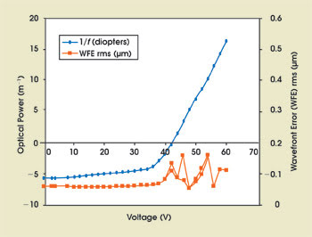
As a focusing actuator, the liquid lens has unique characteristics that make it well suited for open-loop control (Figure 1). Consider an open-loop imaging system where focusing is performed by the liquid lens and distance measurement is performed by an external telemeter.

Figure 1. In this typical characterization graph of Varioptic’s Arctic 320 liquid lens, the high focal range, good linearity and low aberrations are essential features for an autofocus actuator. The graph can be stored in the system as a distance vs. voltage look-up table (rms = root mean square).
The lens begins under a voltage V0 (its optical power is P0), and when the system is asked to focus on a different position, the telemeter measures the focusing distance and determines the necessary voltage V1 to reach the optical power P1 on the liquid lens. The time to acquire a sharp image on the sensor is called time to focus and is dependent upon the depth of field of the system, i.e., the area around the focusing distance in which the image is sharp.
Depth of field can be defined in different ways, the most common being the range in which an object appears sharp when the system focuses at a given distance. This distance range can be converted easily into an optical power range given that the optical power in diopters is the inverse of the distance in meters.
Using the pixel size of the sensor, the maximal spot diameter allowed on the sensor to be sensor-limited can be calculated. One commonly used criterion in color imaging defines the admitted maximal spot diameter as twice the pixel size, but other criteria can be chosen from the allowed contrast loss specification of the system. Here the common criterion of two times the pixel size will be used.
With this criterion, simple geometrical optics can be used to compute the depth of field in diopters with the following formula:

Using this formula, we calculated the depth of field for some classical imaging systems. A mobile phone camera module with an effective focal length (EFL) of 5 mm, an f/2.8 aperture and 2.2-μm pixel size would have a depth of field of 1 diopter. A long-range data capture device with an effective focal length of 20 mm, an f/8 aperture and 6-μm pixel size would have a 0.5-diopter depth of field, and a bar-code reader with an effective focal length of 5.7 mm, an f/5.6 aperture and 4-μm pixels would have a depth of field of 2.8 diopters.
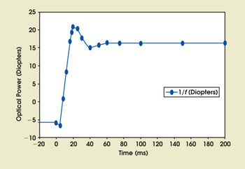
For a given target optical power of the liquid lens, the depth of field yields a range of optical power around this target in which any object will appear in focus on the sensor. In other words, for a target optical power P0, the focus will be reached when the liquid lens reaches and stays within P0 + (0.5 × DOF); P0 – (0.5 × DOF) (Figure 2).

Figure 2. This graph shows the time to reach a 1-diopter depth of field.
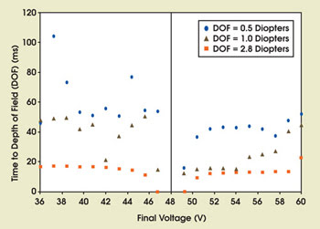
We set the starting voltage (V0) to 48 V, which is in the center of the useful driving voltage range. This is considered to be the best position to reach any voltage between 38 and 60 V with minimal steps. We measured the dynamic behavior of the lenses with a setup using a very fast wavefront sensor with 1-ms time resolution. We focused our study on the common systems described above and measured the time to reach depth of fields of 0.5, 1.0 and 2.8 diopters around several voltage targets (Figure 3).

Figure 3. The results of time-to-depth-of-field experiments performed on Arctic 320, from a start voltage of 48 V to various final voltages, are shown. The time to reach depth of field is measured for a depth of field of 0.5, 1.0 and 2.8 diopters at room temperature (WFE = wavefront error).
Time to focus more than 60 ms in the case of a small depth of field is caused by oscillations in lens response as described in Figure 2.
These results show that for a typical short-range bar-code reading application with a 2.8-diopter depth of field, time to focus of less than 25 ms is achievable over the useful optical power range.
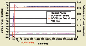
Researchers have investigated ways of improving time to focus for smaller depths of field, and results show that overshooting is the most promising approach (Figure 4). In the figure, a 50- to 55-V step is applied to a liquid lens, with an overshoot at 55.7 V during the first 20 ms of the step. The target depth of field is 0.5 diopters. In this example, the time to depth of field has been reduced from 50 to 10 ms.

Figure 4. Overshooting is an efficient way to reduce time to depth of field (TTDOF)(here, 10 ms instead of 50 ms).
This experiment demonstrates that overshooting provides more energy to the lens at the start of the step so it can reach the depth of field faster. As the wavefront error of the lens stays low (hence, the optical quality of the module stays high) during the step, the device can acquire an image as soon as the target depth of field is reached.
However, defining an overshooting law that is valid for every voltage step depends on the characteristics of the system, such as depth of field or required optical power range. Overshooting is definitely an option to accelerate time to focus but it needs special development to fit a specific application.
Varioptic has demonstrated that liquid lens performance meets requirements for open-loop control systems for applications such as a short-range bar-code reading where time to focus of less than 25 ms is achievable over the useful optical power range. This performance, combined with their robustness, makes liquid lenses a solution for a wide range of applications requiring open-loop control.
Meet the author
Olivier Jacques-Sermet is an optical engineer at Varioptic SA in Lyon, France; e-mail: [email protected].