To ensure successful real-world manufacturing, lens designers must learn how to close the loop between design and fabrication.
KATIE SCHWERTZ AND SHELBY AMENT, EDMUND OPTICS INC.
From time to time, a lens assembly that appears successful in the software stage encounters roadblocks once moved to manufacturing, assembly, and testing. Closing the loop between design and fabrication will result in fewer
design iterations and improved real-world
performance. Optical designers must
consider aspects such as the manufacturability of individual lens elements, manufacturing assumptions made in statistical distributions, surface irregularity models used, and stackups used in tolerancing.
Courtesy of Edmund Optics.
Manufacturability: lens geometry
Although optical design software provides tools to constrain lens geometries,
it does not issue warnings or block solutions that are difficult or impossible to manufacture. Care must therefore be taken during the design stage to ensure a lens is manufacturable, based on both commonly accepted guidelines and communications with the specific optics manufacturer.
When traditionally fabricating a lens
made of glass or other crystalline materials, optics manufacturers will generally begin with a diameter larger than the specification to account for material removed later during centering. To avoid a sharp lens edge during this early phase, maintaining a minimum of ~0.7-mm
edge thickness at 1 mm larger than the final diameter during design is a good rule of thumb.
To reduce difficulty in fabrication and
testing, radii should not become near hemispherical (where the radius of curvature falls below ~0.7× the diameter) or near flat (where the sag of the surface falls below ~100 µm). For biconvex and biconcave elements, to prevent errors in the orientation during assembly, radii that are similar but not exactly the same should be avoided.
The Karow factor, sometimes referred to as the Z-factor or referenced as a gliding or tangent angle calculation, is a lesser-known but important consideration for a successful lens design. It describes the ability of a lens to automatically center itself between bell chucks (also referred to as bell clamps) during centering and is related to the tangent angle of the bell chucks on the surface of the lens1. The Karow factor (Z) is given by:

D1 and D2 are the diameters of the bell chucks being used (typically the same as the clear aperture of the lens). R1 and R2 are the radii of the first and second surfaces. Convex surfaces have positive radii and concave surfaces have negative radii (Figure 1).
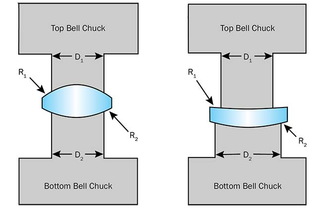
Figure 1. The lens on the left has a higher Karow factor (Z = 2.5) than the lens on the right (Z = 0.4). This means the lens on the left will be easier to center through automated bell-chucking. Courtesy of Edmund Optics.
Generally, if the Karow factor (Z) remains above 0.56, the automated bell-chucking method can be used for centering. Lenses with a Karow factor below 0.56 are still manufacturable but will require a manual process for centering. A manual process is more time intensive, will require more operator time, and will ultimately be significantly more expensive. It can be difficult to develop a design in which the Karow factor remains >0.56 for all elements, but for lenses that are near the limit, the factor may be worth constraining toward the end stages of design.
Another geometrical consideration for lens centering is concentricity of the radii of curvature for meniscus lenses. If these radii are nearly concentric, the lens will be difficult to center since a large amount of material must be removed to correct
for any decentering of the surfaces relative to each other. Concentricity of the radii is evaluated using the following equation:

R1 is the radius of the side that is farther from the centers of curvature, R2 is the radius of the side that is closer to the centers of curvature, and CT is the center thickness of the lens (Figure 2). The rule of thumb to follow is |Δr| >2 mm.
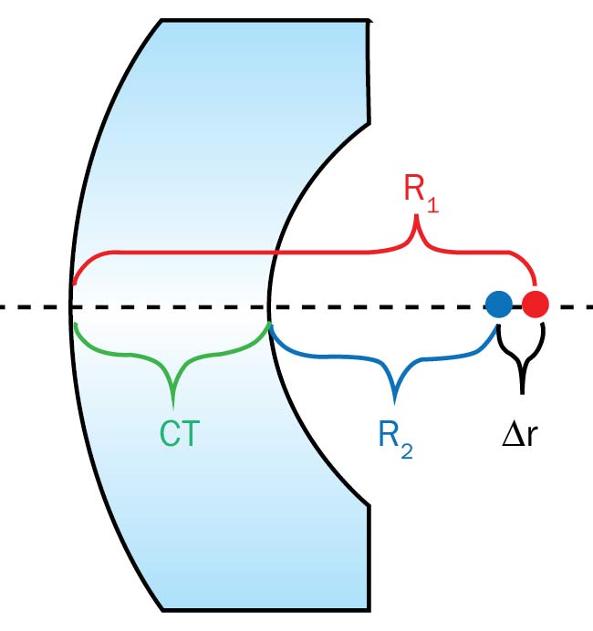
Figure 2. A meniscus lens with radii that are nearly concentric. To ensure that the lens can be centered during manufacturing, |Δr| should be >2 mm.
CT: center thickness. Courtesy of Edmund Optics.
As with any general guidelines, there will be exceptions, most notably for especially small or large optics and extreme environmental or performance requirements. Expect most optics ranging from approximately 3 to 75 mm in diameter to follow the guidelines above.
Tolerancing assumptions
It’s well-known that big data and
analytics can improve processes or understanding of a particular phenomenon2. Over the past decade, the optics industry has been paying more attention to manufacturing data and its applicability to lens design3. Given that probability-based Monte Carlo analysis is still the predominant method of predicting an optical system’s as-built performance, it is important to take care in understanding the statistical inputs.
The center thickness of a lens provides
a simple example. Many optics manufacturers will err on the side of keeping a lens on the thick side of the tolerance throughout the early stages of fabrication. This allows margin for correcting errors later in the process. Such errors include surface figure or scratch-dig, which reduce the center thickness of the part without violating the minimum thickness requirement. The result is often that the distribution of a set of optics will be skewed to the high side of the tolerance (Figure 3). In a Monte Carlo analysis, however, it is often assumed that center thickness tolerances follow a symmetric (normal or uniform) distribution.
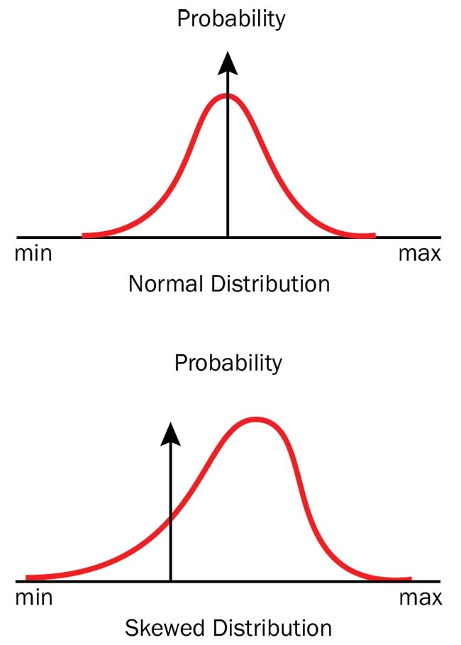
Figure 3. The center thickness of a lens will often be oversized to allow for corrections later, leading to a skewed distribution of center thickness values. Courtesy of Edmund Optics.
A variety of factors can influence the true tolerance distribution of a set of lenses, including the tightness of a set of tolerances, the fabrication process (diamond turning vs. batch processing), the lot size, and even a manufacturer’s or technician’s style. Whether or not this level of fidelity is required for a particular application depends greatly on the required complexity of the system and on the precision in prediction. A sensitivity analysis of the optical system can highlight which tolerances are the most important to model with higher fidelity.
The benefits of understanding manufacturing tolerance distributions extend well beyond optical design. Developing a better understanding of one’s own internal distributions or that of a vendor base can provide an excellent way to compare supplier performance, avoid no-bids, and highlight potential cost savings.
Surface irregularity model
Surface irregularity of a spherical lens can be modeled in lens design software in a variety of ways4,5. Two typical built-in models are a 50-50 combination of spherical aberration and astigmatism, and 100 percent astigmatism.
Because spherical aberration is rotationally symmetric, this portion of irregularity can be partially compensated with defocus, while astigmatism does not have a similar compensator adjustment.
The irregularity model used can significantly impact the result of a Monte Carlo tolerance analysis. Consider a six-element imaging lens modeled with 1/4 wave of irregularity on all surfaces. The system is refocused to minimize transmitted wavefront error, and modulation transfer function (MTF) is evaluated. Two irregularity models are compared: a 50-50 combination of spherical aberration and astigmatism at a random clocking orientation, and 100 percent astigmatism at a random clocking orientation. The graphs show that the 100 percent astigmatism model is more detrimental to this system’s performance (Figure 4).
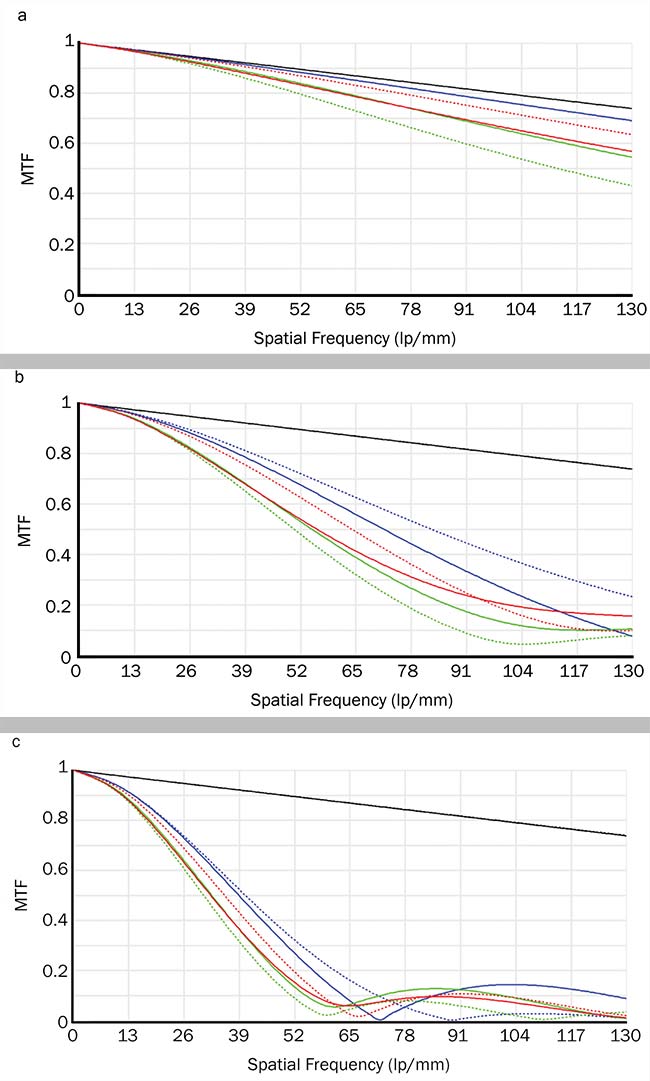
Figure 4. Nominal system modulation transfer function (MTF) (a); 1/4 wave peak-to-valley (PV) irregularity on all surfaces, modeled as 50 percent spherical aberration and 50 percent astigmatism with a random clocking orientation (b); 1/4 wave PV irregularity on all surfaces, modeled as astigmatism with a random clocking orientation (c). Courtesy of Edmund Optics.
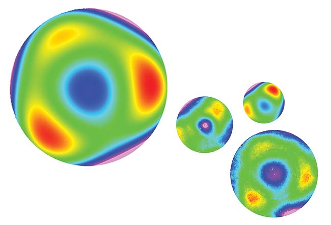
Real surface irregularity maps will differ from the simplified models discussed above. For systems that are sensitive to irregularity, it may be necessary to use a higher fidelity model, such as one based on Zernike polynomials. If a set of real irregularity maps are fit to Zernike coefficients, these coefficients can be used in a more advanced irregularity model (Figure 5). A set of tolerance operands can be set up in design software with the same ratio of Zernike coefficients. By incorporating measured irregularity features into the tolerance model, higher accuracy in predicted optical performance can be achieved.
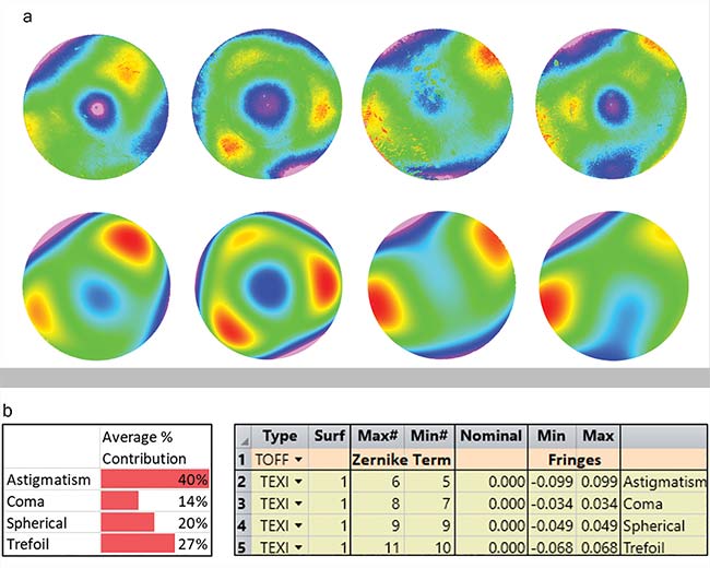
Figure 5. Four measured surface irregularity maps based on the 5th to 11th Zernike coefficients and the approximated models of these maps using several Zernike coefficients below them (a). Relative contribution of each Zernike coefficient to the irregularity maps (absolute value, averaged over all maps) and a list of tolerance operands set up in Zemax OpticStudio that maintains this ratio of Zernike coefficients on a particular surface (b). Courtesy of Edmund Optics.
Drop-together systems
In drop-together optical systems where
elements are loaded into a barrel without further adjustment, the wedge in lens elements and spacers will contribute to the tilt and decenter of subsequent elements as the system is being assembled. To model these systems correctly in a tolerance analysis, the model should be set up so that each Monte Carlo iteration includes the correct stackup of element tilts based on how the lens is assembled (Figure 6).
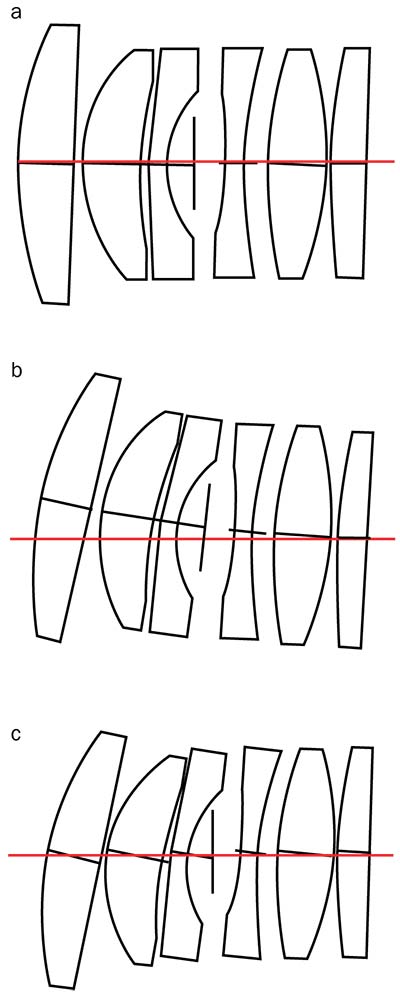
Figure 6. Three approaches to lens element tilt in a drop-together assembly. All elements are tilted by 2° in the same direction to more easily illustrate the differences. Lens element tilts are modeled independently (a). Lens element tilts and decentration are accumulated in the order of assembly (b). Lens element tilts are accumulated in the order of assembly, with no additional decentration (c). Courtesy of Edmund Optics.
In the first case, element tilts are not accumulated. This is a simple way to model the system, but it will not capture stackup effects. In the second case, tilts are accumulated and the elements are allowed to tilt and decenter as the stack grows. This is a more accurate motion for a drop-together system, but it leads to the possibility that some lenses may fall outside of the barrel on a particular Monte Carlo run. To keep this from happening,
the third case models accumulation of tilts but forces lens elements to stay centered on the optical axis. This motion is called shearing.
The lens designer must pick the model that is most feasible, given the system
geometry, assembly method, and tolerance values. If the optical system is a drop-together lens assembly with a very small bore gap (the space between the outer diameter of a lens element and the inner diameter of a barrel), the third tilt model would be a good choice. For a system with looser tolerances and low sensitivity, the first tilt model may be sufficient.
Two other motions to consider in drop-together assemblies are decentration and roll of lens elements due to the bore gap (Figure 7). Consider a lens element resting on a spacer. If the lens has a convex surface in contact with the spacer, the bore gap will allow a roll motion. Roll is
a rotation of the lens about the vertex of its radius of curvature. If, however, the lens has a flat annulus or planar optical surface in contact with the spacer, the bore gap will allow decenter motion.
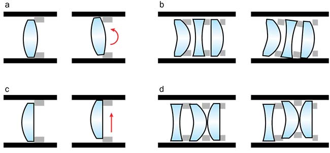
Figure 7. Bore gap lens dynamics. Roll motion of an element with convex rear surface (a). Coupled roll motion (b). Decenter motion of an element with planar rear surface (c). Coupled decenter motion (d). Courtesy of Edmund Optics.
Roll and decenter of an element can also affect subsequent elements in the barrel. In the case of roll, all subsequent elements will be coupled to the rolling element and move with it. In the case
of decenter, only elements with convex rear surfaces contacting spacers are coupled. Elements with an annulus or
flat optical surface resting against the spacer can move independently of the initial decentered element.
The level of detail required to model these lens motions during tolerancing
and its effect on performance depend on the sensitivity of the optical system to tilts and decenters. Going through the
tolerancing process with this level of
fidelity can also aid the designer in
rethinking the assembly process. Lens elements may be assembled in a different order, multiple lens seats may be created, or elements could be grouped together into subcell assemblies.
It is easy to believe a successful solution to an optical design problem has been found, only to later get feedback on manufacturability constraints that require a redesign — or worse, to observe a yield that is much lower than expected, without a clear path forward for improvement. Increasing the accuracy of the system model and tolerancing statistics during the design phase will take effort up front, but it will ultimately save a great deal of time and money in the long run.
Meet the authors
Katie Schwertz is a senior optical designer at Edmund Optics in the Tucson, Ariz., office. She is responsible for rapid development
of optical and mechanical designs for both
catalog and custom applications; email:
[email protected].
Shelby Ament is an optical research
engineer at Edmund Optics in the Barrington, N.J., office. She is responsible for developing
new optical metrology and fabrication
techniques to improve Edmund Optics’ manufacturing capabilities; email: [email protected].
References
1. H.H. Karow (2004). Fabrication Methods
for Precision Optics. J. Wiley & Sons, Inc.
2. R. Bean (April 28, 2017). How Companies Say They’re Using Big Data. Harvard
Business Review, https://hbr.org/2017/04/how-companies-say-theyre-using-big-data.
3. M.I. Kaufman et al. (September 19, 2014). Statistical distributions from lens manufacturing data, Proc SPIE 9195, Optical System Alignment, Tolerancing, and Verification VIII, 919507, https://doi.org/10.1117/12.2064582.
4. Zemax LLC (2018). Zemax OpticStudio
18.4 User Manual. Kirkland, Wash.
5. Synopsys (2018). CODE V Tolerancing
Reference Manual. Mountain View, Calif.