For imaging applications, it’s important to know what kind of noise you’re dealing with.
Dr. Gerhard Holst, PCO AG
In digital imaging applications, noise is commonly assumed to be bad, a characteristic that makes images worse. Although many types of noise are known, their origin and, more importantly, their impact on images is often misunderstood.

Figure 1. These black-and-white images show the same scene. The white line indicates the position of the single pixel row used to create line readouts for the graph in Figure 3.
One way to judge noise is to view images. For example, Figure 1 shows two monochrome images with gray levels that appear similar. Although these images look the same, when a section of each is enlarged, there is an obvious difference between the two (Figure 2). Because the image on the right clearly shows significant graininess — a visible consequence of noise — one would think that the camera that took the right-hand image had more noise.
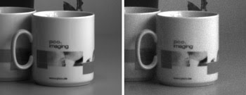
Figure 2. These enlarged views correspond to the black-and-white images in Figure 1.
Another way to compare noise in cameras is to analyze the readout of single lines. Reading out and graphically displaying the gray-level counts from a single pixel row from each image (represented by the white lines in Figure 1) creates two graphs (Figure 3). Presented over a span of 900 counts, the absolute values appear to be different. If the width of the line is used to estimate noise, the noise in the graph on the left is apparently much greater.
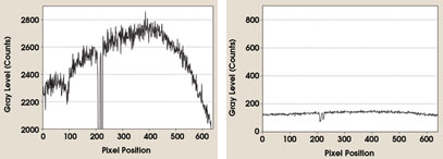
Figure 3. These graphs are line readouts from the single pixel rows corresponding to the black-and-white images in Figure 1.
Each image examination leads to a different conclusion. So which of the two cameras has more noise?
Different effects
In fact, the same camera was used to capture both images, but different settings were used for each. The left-hand image was recorded at f/5.6 with an exposure time of 15 ms, while the image on the right was recorded at f/11 with 1 ms exposure time. This exercise demonstrates that various sources of noise can have different effects even when the same camera is used.
The image recording process in a digital camera system involves several steps. Light is imaged by one or more lenses onto a digital image sensor. There, it interacts with the semiconductor and generates charge carriers (electrons) that are transported out of the image sensor. The charge carriers are converted into voltages and into digital numbers (counts) by an analog-to-digital process. During this process, many factors reduce the signal quality and, in turn, the image quality. These influences are generally referred to as noise, and they all contribute to the visual manifestations of noise that are seen in Figures 1 to 3.
Ideally, if an image sensor had a quantum efficiency of 100 percent, each photon would generate a charge carrier in the sensor (in this case, electrons in a CCD) resulting in the ideal photon/electron relationship indicated by the black line in Figure 4. The actual image sensor allows for only 50 percent quantum efficiency (blue area), which is limited by the horizontal dark blue dotted line. This line denotes the full-well capacity, the maximum for the charge bucket of the CCD.
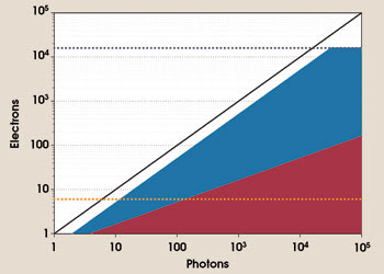
Figure 4. This graph shows the relationship between the charge carriers (electrons) generated in a digital image sensor and impinging photons. The black line represents the ideal relationship between electrons and photons, assuming a quantum efficiency of 100 percent. The horizontal dark-blue dotted line indicates the limit given by thefull-well capacity of a CCD image sensor (15,974 e–). The horizontal orange dotted line shows the limit given by the root mean square readout noise of a camera (6 e–). The shape of the red area represents the photon noise, assuming a quantum efficiency of 50 percent, and the shape of the blue area depicts light signal, assuming a quantum efficiency of 50 percent.
Because of its statistical nature, light can best be described by a probability distribution. This means that, even under identical light levels, there exists an uncertainty about the amount of photons that hit the pixel. This uncertainty, called photon, or shot, noise (shown by the red area in Figure 4), equals the square root of the number of electrons.
The image sensor also contributes noise from the thermal movement of charge carriers, shift-induced charges or from other sources. Further, the camera system’s readout circuit will accumulate the noise generated by its own components (represented by the horizontal dark red dotted line in Figure 4). This noise is constant and should be independent of the light signal.
At ~80 photons, the readout noise equals the photon noise. Below that point, the readout noise is greater and is considered dominant, while above that point, the photon noise becomes increasingly dominant.
What does this mean for imaging? At low light intensities, the camera’s readout noise determines the image quality. Even with an adequate signal, the signal’s photon noise determines and limits the noise performance if the camera does not filter or distort the image process. It is difficult to correlate the electrons-vs.-photons graph to actual imaging applications, which usually result in digital number (or count) distributions in an image.
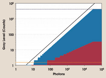
Figure 5. This graphical display shows the relationship between gray levels of a digital camera (counts) and impinging photons. The technical limits (assuming an A/D conversion of 12 bits) correspond to the data from Figure 4 and use a conversion factor of 3.9 [e–/count]. The black line identifies the ideal relationship between gray levels and photons, assuming a quantum efficiency of 100 percent. The horizontal dark-blue dotted line indicates the limit given by the full-well capacity of a CCD image sensor (4096 counts). The horizontal orange dotted line represents the limit given by the root mean square readout noise of a camera (1.5 counts). The shape of the red area indicates the photon noise, assuming a quantum efficiency of 50 percent, and the shape of the blue area depicts the light signal, assuming a quantum efficiency of 50 percent.
Figure 5 shows the same image sensor and relationship but after an analog-to-digital conversion with a 12-bit converter, using a conversion factor of 3.9 [e–/count]. Again, the black line depicts quantum efficiency of 100 percent, now shown as gray levels. The full-well capacity is the maximum value of 12 bits (4096 counts), and the signal is represented by the shape of the blue area, with distinct conversion steps evident at the darker end of the image scale (one to 10 counts). Photon noise is depicted by the shape of the red area and readout noise, by the horizontal dark-red dotted line. The A/D converter has a 0.5-bit uncertainty, which is not shown. It takes more than 10 photons to cause the count value to move above one in the image. The upper limit, defined by the full-well capacity, also gives the maximum white value (4096 counts).
It is important to note that, in an actual camera system, measurement settings do not begin at one count but rather at an offset (also called “black shoulder” in video cameras) to allow for a proper dark noise determination. The offset can be a little larger than the root mean square noise in a single image. Therefore, the usable dynamic range could be slightly smaller.
Because there are some clear absolute values in our example, it would seem that there would be a huge amount of noise if the signal were to rise. Although this is correct, its impact is not detrimental, as the more important number is the signal-to-noise ratio (SNR), which results from the relationships in Figure 5.
Taking the data from Figures 4 and 5, we can calculate the SNR, which is presented in Figure 6. Again, the black line indicates the maximum possible SNR, with no camera noise and an assumed quantum efficiency value of 100 percent. The actual SNR, the blue curve, runs parallel to the ideal curve above 1000 photons until the clipping starts. It is obvious that, in this mode, the camera is limited by the light-inherent noise. Below 1000 photons, the curve starts to distort because of the increased contribution from the readout noise.
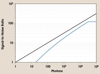
Figure 6. This graph shows the signal-to-noise ratio vs. impinging photons of the same camera, as in Figures 4 and 5. The black line indicates the best possible signal-to-noise ratio, assuming that no noise other than photon noise is present. The blue line represents the signal-to-noise ratio calculated from a CCD image sensor with a 50 percent quantum efficiency, 6 e– rms readout noise, 15,974 e– full-well capacity and photon noise.
Even when near the maximum possible signal, the SNR is between 100 and 200. This means that the best achievable dynamic per pixel is between 7 and 8 bits, from the signal noise. Provided that the camera is operated in that range, it can be increased only by a higher full-well capacity because the readout noise has virtually no effect.
Conclusions
Returning to the question raised at the beginning of the article — Which camera has more noise? — the answer is dependent on the amount of light in a particular imaging application. In the case of low light, the visible noise showing a bad SNR is mostly determined by the readout noise. Therefore, if images are to be taken in low light, such as in biological or medical applications, microscopy, security or night vision, the camera system’s readout noise is an important consideration when making a camera selection. In this case, noise is a bad parameter and should be as small as possible.
With large amounts of light, a good SNR should be achieved, and the emphasis should be on a high full-well capacity, which usually corresponds to a pixel with large light-sensitive areas. In this case, for the best images, the signal and, therefore, the photon noise should be as large as possible. Indirectly, noise is a good parameter and should be recorded by the camera without further filtering or process influences.
A variety of noise and light detection models and explanations are available in print.1 A new European Machine Vision Association standard has been published,2 which should help imaging system users select the appropriate camera more easily.
In imaging, it’s not about the good noise and the bad noise, it’s about the right noise.
Meet the author
Gerhard Holst is an electronics engineer and head of the research department at PCO AG in Kelheim, Germany; e-mail: [email protected].
References
1. J.R. Janesick (2001). Scientific charge-coupled devices. SPIE Press, Bellingham, Wash.
2. 1288 EMVA standard for characterization and presentation of specification data for image sensors and cameras. 2005. European Machine Vision Association. www.emva.org.