Simulation tools minimize the cost and time associated with iterative hardware prototyping and clinical testing.
MICHAEL GAUVIN, LAMBDA RESEARCH CORP.
Pulse oximetry has been used since the 1970s, and has been widely adopted by hospitals to monitor oxygen (O2) saturation and pulse rate (PR) by attaching devices to a patient’s fingertip, forehead or earlobe. The application for these devices has remained virtually unchanged for more than 40 years; however, the growing interest in “wearables” has taken pulse oximetry out of the hospital and into the general consumer market.
Device designers in Europe developing innovative pulse oximetry devices — such as Withings Pulse wireless activity tracker — face unique design challenges: balancing measurement accuracy with stylish form factors that are desirable to the wearer. Prototyping these devices is costly and time-consuming. What device engineers require is a more efficient method of accurately simulating the intensity of light being absorbed by human tissue.

Precise measurement of O2 saturation and PR requires an understanding of the absorbance of each wavelength of light in proportion to the concentration of tissue and blood, as well as in proportion to the length of the light path. An additional factor is the reduction of the bias in these measurements in order to improve accuracy. This can vary greatly based upon low levels of saturation and concentration caused by anemia or other vascular conditions, and the quality of the signal-to-noise ratio between the device optical elements.
There are two methods of pulse oximetry: transmission and reflection. Devices using the transmission method have a vertical orientation between the LED source and the photodetector. The light (red and infrared) passes through or is blocked by the tissue between the two optical elements. The reflection method requires the LED source and the photodetector to be on the same surface, whereas the light passes through the tissue at a set angle. In the case of wearables, this surface may be concave, making the angle between the optical elements variable.
In the reflection method used in wearables, multiple challenges face the designer. These start with the choice of LED manufacturer, the specific LED wavelengths needed for accurate measurement, as well as placement and distance of the LED sources and the photodiode.
Just recently, designers were on their own when it came to creating the source and detector package for a wearable. The latest approach features three wavelength sources with unique sensor geometry and improved algorithms for enhanced performance. This configuration is less susceptible to poor signal-to-noise conditions when compared to existing reflection oximetry systems. LED supplier OSRAM GmbH has an all-in-one sensor featuring three LEDs emitting at 940 (infrared), 655 (red) and 530 (green) nm, and a photodiode in an extremely small package, 4.7 mm × 2.5 mm × .9 mm with a light barrier to block optical crosstalk and improve accuracy of the signal. The OSRAM biosensor is a suitable off-the-shelf component for monitoring pulse rate and providing pulse oximetry information for a wearable. But there is quite a bit more to design even with this new biosensor technology, including: electronics, display and wearability. Balancing the technical aspects of the design with the aesthetic demands of the consumer means that designers need a virtual way to quickly create form factors, simulate performance, optimize design and only then move to physical prototyping1.
Instead of creating designs using standard trial-and-error prototyping that takes time in manufacturing, testing and then redesigning to meet criteria through manufacture, TracePro creates a 3D interactive virtual prototyping environment to iterate designs quickly and efficiently. This significantly reduces prototyping costs and creates a better product. It substantially reduces time to market, eliminates multiple testing costs and creates better designs in less time.
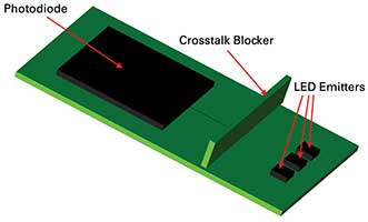
Figure 1. Simulated chip created in TracePro virtual simulation optical and illumination software. Courtesy of Lambda Research Corp.
The placement and distance of the LED sources and photodiode detector around the band are important. In order to accurately measure tissue oxygenation using the reflection method, the light exiting from the LEDs enters the skin tissue and curves through to interact with the oxygenated tissue before propagating to the photodiode. To stop false signal from the direct path of light going from the LED sources to the photodiode, a light barrier is introduced to stop this stray light, which would cause a false reading. Other stray light problems occur if the wearable is not snug against the human body, as this potentially allows outside sources to propagate to the wearable photodiode. Possible stray light sources include direct and indirect sunlight, and indoor ambient lighting. If these sources reach the wearable’s photodiode, a false signal can completely overwhelm the device and inaccurate results occur. To stop these stray light sources, additional material is needed to either block the outside source or absorb the light before it can propagate to the photodiode. Most wearable bands are made out of dark or opaque material, which stops much of the stray light from reaching the photodiode.
Device engineers involved in the product development of pulse oximetry wearables should consider the use of optical simulation tools to predict performance that improves accuracy and conveyance of health information. By taking their designs directly from their CAD system, device engineers can validate their opto-mechanical design and develop processes though virtual prototyping by communicating design elements and system performance across disciplines — optics, mechanics, materials, chemistry and biology — to both scientists and production engineers.
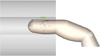
Figure 2. Side profile of the rays emitting from the LEDs to the photodiode on top. Courtesy of Lambda Research Corp.
Fewer prototypes required
Simulation tools minimize the cost and time associated with iterative hardware prototyping and laboratory and clinical testing. Models are created by directly creating the solid geometry within the tool or by importing from a CAD program. Sources can be created as propagating from a surface with both wavelength and angle specifications or raysets produced from measurements and downloaded directly from the LED manufacturer. Source rays are then propagated through the model with portions of the flux of each ray allocated for absorption, specular reflection, transmission, fluorescence and scattering. Visualization of problem areas can be combined with quantitative study of both cross-talk and stray light issues in order to validate the design. This creation of a virtual 3D CAD model with correctly applied optical properties can then be ray traced to give the designer the capability to visualize and quantify what is happening inside the device to assess problematic design flaws before physical prototyping. The designer can then iterate the design interactively by specifying variables, including LED position and angle, stray light suppression mechanisms, and also set a desired merit function that the simulation program can optimize.
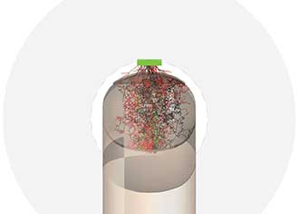
Figure 3. End of view showing rays from all three LEDs reaching the photodiode. Courtesy of Lambda Research Corp.
Let’s evaluate two devices using an optical simulation prototyping tool: TracePro, from Lambda Research Corp. In the first simulation, a commonly used finger pulse oximeter that one would see in a hospital to monitor blood oxygenation and supply pulse rate was tested. This device uses transmission to propagate either two or three LEDs positioned on the bottom of the device to emit through the finger to the photodiode on top. By using three LEDs emitting at 520, 650 and 940 nm, the designer knows ahead of time that the three source setups allow the photodiode to autocorrect the signal and is generally more accurate than two LED setups.
Next, the designer selects tissue from a materials catalog to quickly and easily define the bulk scatter that occurs in the finger. The software uses the Henyey-Greenstein phase function to model bulk scattering of light through the finger tissue. After tracing rays, it is a simple process to visually sort only those rays that reach the photodiode. This simulation is shown in Figure 2, with each LED source emission in green for the 520-nm emitting LED, red for the 650-nm LED and black for the IR LED. Light mainly scatters forward in the upward direction from the LEDs, but bulk scattering takes a circuitous route through the finger to finally reach the photodiode at the top.
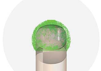
Figure 4. Simulation showing rays propagating from the green LED along the inner pulse oximeter surface. Courtesy of Lambda Research Corp.
An end-on view of the same ray trace quite easily shows the route taken. While this may not seem to be the case, this is actually a good thing, since the bone in the finger blocks light. This ray trace shows that light has been able to travel around this obstruction, and was received at the photodiode.
Light does not propagate around the sides of the pulse oximeter to the photodiode (Figure 3). For this first simulation, the inside of the pulse oximeter was coated with an absorbing black paint that prevents light from traveling around the inner surface to the photodiode.
Covering the same system with a white reflective plastic coating inside the surface of the pulse oximeter yields a different result. This simulation only uses the green LED as a source for ease of demonstration. As seen in Figure 4, light emitted from the green LEDs reflects around the inside of the pulse oximeter’s reflective surface to reach the photodiode.
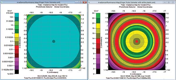
Figure 5. Irradiance maps showing the contribution of direct signal versus stray light as shown in Figures 3 and 4. Courtesy of Lambda Research Corp.
Figure 5 demonstrates the irradiance maps for the two specific paths shown graphically in Figures 3 and 4. The map of the left shows the signal from the three LEDs reaching the photodiode only by bulk scattering through finger tissue (Figure 3). The map on the right shows the false signal contribution of the light path originating from the LEDs that reflect and scatter around the finger, off the white plastic to the photodiode. Comparing the two irradiance maps reveals the desired signal path through the finger tissue; it’s an order of magnitude larger than the stray light contribution of light scattering and reflecting off and around the finger. A stray light contribution of 10 percent is acceptable in most standard pulse oximeters today, but this path could have been removed if the designer used an absorbing black or diffuse white plastic to absorb or further scramble this stray light contribution.
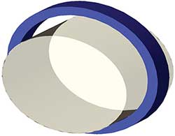
Figure 6. TracePro model of wearable with wrist tissue. Courtesy of Lambda Research Corp.
The second virtual prototyping simulation tests a reflective wearable setup. Here, the system emits at the three previously mentioned wavelengths and enters the tissue following a curved light path to reach the photodiode on the same surface. The crosstalk barrier in-between is crucial to stop the direct stray light path.
Of the three paths by which light can propagate from the LEDs to the photodiode in a wrist wearable, only one is the desired path, as shown in the cross section of the LED and photodiode chip and the epidermis layer of the skin (Figure 7). The first path slips under the crosstalk blocker between the LED and photodiode. This is possible because the blocker is embedded in clear material and has lifted off the PCB during the cooling process of the embedding material. The second path goes over the blocker and hits the epidermis layer of the skin, scattering directly to the photodiode without entering the wrist tissue. This path will occur in a wearable that is not fixed firmly to the skin using either a watchband with clasp or locking method to secure it. To overcome this, make sure the blocker is always in contact with the skin, or use electronic methods to remove the erroneous signal from the pulse oxygenation measurement. The third path is the correct path; LED light enters the skin and bulk scatters through a curved trajectory to reach the photodiode.
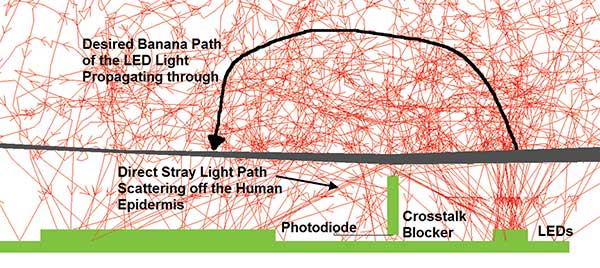
Figure 7. Blown-up view of the light emitting from the LEDs and the three paths to the photodiode. Courtesy of Lambda Research Corp.
Wearable device manufacturers must find the balance between form and function in order to appeal to consumers who demand data and style. The speed at which these products must be brought to market dictates that traditional prototyping processes must be replaced with virtual simulation tools. With highly accurate performance predictions and optimization functions, designers are free to conceptualize new designs and generate consumer demand limitlessly.
For designers, the big picture is inventing smaller, more lightweight, better wearable devices that don’t break under use. Users of wearable technology will continue to ask for highly reliable and accurate pulse oximetry measurement in one device. The all-in-one chip concept helps immensely in reaching these goals, but it is not the final solution to stop stray light problems and produce a reliable measuring device. Software simulation is needed to reduce costs and provide validation of new devices before going to costly trial-and-error prototyping.
Reference
1. Y. Mendelson et al. (January 2002). Multi-wavelength reflectance pulse oximetry. Anesth Analg, 1 Suppl., pp. S26-30.
Meet the author
Michael Gauvin is the vice president of sales and marketing at Lambda Research Corp., with over 30 years of optical engineering experience. He has designed illumination systems and implemented stray light studies. Gauvin has worked on stray light analysis of the Hubble Space Telescope, the design of the light pipe for the second-generation Microsoft mouse, and the Bionix Ear Curette that won the MDEA award for design excellence.