Advances in liquid crystal and liquid crystal polymer materials have made it possible to modulate the orientation of the anisotropy axis at high spatial frequencies, ushering in the next generation of optics for space communications and intraocular lenses.
NELSON TABIRYAN AND DAVID ROBERTS, BEAM ENGINEERING FOR ADVANCED MEASUREMENTS, DIANE STEEVES AND BRIAN KIMBALL, U.S. ARMY NATICK SOLDIER RD&E CENTER
From the advent of the candle to the emergence the first laser diode, there have been numerous advances in light sources. After all, all materials radiate when energized one way or another.
Optics, however, have undergone a slow evolution.
There are only a few ways to control light. Isotropic materials such as glass modulate shape or take advantage of the refractive index. The first case serves as the foundation for the first generation of optics, and is still overwhelmingly in use today given the capability of strongly influencing light propagation in a broad band of wavelengths.
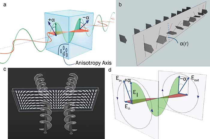
Figure 1. Modulation of optical phase
due to spatial modulation of the anisotropy axis orientation of a
half-wave retardation plate. Rotation of linear polarization of light
upon passage through a half-wave plate (a). The green
and red sinusoids depict the electric field components of a beam
polarized along and perpendicular to the anisotropy axis; a is the angle
the linear polarization axis makes with the anisotropy axis at the
entrance to the film. Modulation of light polarization by a half-wave
plate with optical axis orientation angle varying along a transverse
Cartesian coordinate (b). Diffraction of light by a
half-wave plate with linear spatial modulation of the optical axis
orientation; a right- or left-circularly polarized light beam diffracts
into +1st or -1st order depending on sign (c).
Visualization of the 2α geometrical phase-shift between input and output
circular polarized beams due to passage through a half-wave plate (d). Courtesy of Beam Co.
Weight and size, however, limit refractive lenses and prisms to applications that require relatively small optics. Gratings based on modulation of refractive index may exhibit high efficiency in thinner structures, however, compromising bandwidth.
Anisotropic materials offer two more ways to control light. The modern liquid crystal display controls light by modulation of birefringence. The thickness of liquid crystal layers is limited to micrometers due to light scattering and structural defects in thicker layers. Therefore, even with huge optical anisotropy, Δn = nll - n⊥ ~ 0.2 for commercially available materials and Δn = nll - n⊥ ~ 1 for experimental compounds (nll and n⊥ being the principal values of refractive indices of the liquid crystal), the maximum obtainable phase modulation by a liquid crystal due to modulation of birefringence is small for developing lenses or other optical components that could challenge conventional optics.
Modulating transparent anisotropic thin films
Orientation of the anisotropy axis is the only remaining optical parameter to modulate in transparent anisotropic materials. Micrometer-thin material films engineered to have spatially varying orientation of the anisotropy axis constitute the fourth generation of optics (4G optics) that extends the limits of optical and electro-optical systems to extremes in terms of optical strength, bandwidth, aperture size and versatility.
• Optical power — comparable to that of glass optics.
• Bandwidth — encompassing wide portions all over the electromagnetic spectrum.
• Aperture sizes — ranging from micro-meters to meters.
• Weight — determined essentially by substrates’ weight only.
• Manufacturing cost — using low-cost simple equipment and procedures, allowing roll-to-roll fabrication and customization in real time.
• Material cost — driven mostly by substrate cost.
• Versatility — any optical component fabricated using the same materials and processes.
• Fabrication time — processes that could be as fast as nanoseconds and not longer than minutes.
This is made possible due to modulation of the geometrical phase known as the Pancharatnam-Berry phase. The phenomenon, known since the 1950s, remained largely unexplored until liquid crystal and liquid crystal polymer materials made it possible to modulate orientation of the anisotropy axis at high spatial frequencies with high quality in a large area — and using technologically inexpensive processes1,2. Like the breakthrough in displays, liquid crystals are now driving the advances in optics and photonics while other technologies of “flat optics” remain a laboratory fascination due to complexity and cost. The success of liquid crystal technology is largely due to decades of huge investments in liquid crystal display research and development.
Geometrical phase visualized
Half-wave retardation plates are thin anisotropic films commonly used for rotating polarization of a light beam. Choosing the film thickness according to the condition L(nll - n⊥) = λ/2 (λ - wavelength in vacuum) ensures that the slower polarization component of the beam is delayed exactly by one half-wave compared to the faster one. Then the beam at the output of the film remains linearly polarized, making an angle -a with respect to the anisotropy axis, with a being the angle at the input surface (Figure 1a).
Consider now a system of half-wave retardation plates with different orientation of anisotropy axis (Figure 1b). A linearly polarized input results in an output beam with spatially varying polarization. In the case of continuous modulation, α = qx with q = π/Λ determining the spatial period Λ, the polarization at the output with an angle 2α has a twice higher spatial frequency of 2q. The obtained polarization pattern is remarkable; it corresponds to the field in the overlap region of two orthogonally circularly polarized beams propagating at angles of ± λ/Λ with respect to the normal to what effectively is a “diffractive wave plate.” Hence, such a wave plate diffracts a linearly polarized or an unpolarized beam into orthogonal circularly polarized beams (Figure 1c).
Note now that the angle a for a circularly polarized beam is changing in time due to polarization rotation, and there is a 2α phase shift between rotation angles of the output and input beams (Figure 1d). Thus, a half-wave retardation film reverses the polarization handedness of an input circularly polarized beam while also inducing a phase equal to 2α that depends only on orientation of the anisotropy axis of the half-wave retardation film. That is the geometrical phase. A constant phase for a uniform wave plate never mattered. When modulated, though, it opens up a new frontier of optics.
The new world of optics
Simply varying the pattern of anisotropy axis orientation in a wave plate makes it possible to produce all the variety of optical components and functions. The linear modulation pattern a = qx is indeed the simplest and, known as cycloidal diffractive wave plate, acts as a prism (Figure 2a). A parabolic profile, α ~ r2, acts as a lens (Figure 2b). Note that different signs of the phase shift corresponding to different handedness of circular polarization mean different signs of the focal length of such a diffractive wave plate lens: It focuses a beam of one handedness while defocusing the beam of opposite handedness3.
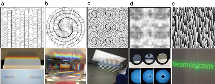
Figure 2. Examples of diffractive wave plates. Top: optical axis orientation patterns presented by a system of continuous lines tangential to the local orientation of the anisotropy axis (a-c), as line segments (d), and as a gray scale varying from 0 (white) to 180° orientation angle (black) (e). Bottom: photographs of devices and optical effects, including a cycloidal diffractive wave plate and diffraction pattern of a black and white image of the word “BEAM” demonstrating practical absence of zero-order over visible spectrum (a); a nonachromatic diffractive wave plate lens demonstrating both focused and defocused images and some zero-order (b); an array of diffractive wave plate lenslets (c); single vector vortex wave plates (d); and a holographic beam shaper designed to convert a Gaussian beam into “beamco.com” with zero-order as the dot (e). Courtesy of Beam Co.
Arrays of optical elements such as lenses and vortices can be designed for which the optical axis orientation is continuous across the boundaries between array elements (Figures 2c and 2d). More complex structures corresponding to a holographic beam shaper are also possible (Figure 2e).
As wave plates, it is no more a wonder that 4G optics are broadband and can be made practically achromatic in a wide range of wavelengths using techniques for fabrication of broadband wave plates4. The diffraction efficiency for those components can exceed 99 percent if properly designed and fabricated.
Fabrication: dielectric coatings with a twist
Forcing continuous deformation of a crystal axis in the microscale is not easy. Fortunately, it is both feasible and technologically cost-effective for liquid crystal materials due to their low elastic energy. Thin films of liquid crystal materials are obtained between substrates with conductive layers for switchable electro-optical systems or as thin polymer film coatings.
In the basis of fabrication is a process known as photoalignment. The substrate is coated by a nanometer thin film of a material (Figure 3a) that generates anisotropy when illuminated by linearly polarized light, with anisotropy axis determined by light polarization (Figure 3b). Certain azobenzene dyes with anisotropic molecules are among the most effective photoalignment materials. The molecules of azobenzene undergoing repetitive photoisomerization end up aligned predominantly perpendicular to the polarization where the absorption is minimized. This process can be induced by UV as well as by visible light of blue-green wavelengths, which is particularly important due to wide availability of high-power lasers for such wavelengths.

Figure 3. Main steps in the diffractive wave plate fabrication process: deposition of photoalignment material and exposure to a polarized light beam (a); photoalignment obtained by spatially patterned, linearly polarized light corresponding, as an example, to the pattern for a diffractive wave plate lens (b); and coating of the alignment layer with liquid crystal polymer that adopts the orientation pattern recorded in the photoalignment layer (c). Courtesy of Beam Co.
Due to thinness, the photoalignment layer itself does not affect the optical properties of the system; however, it proves adequate for inducing alignment of a few micrometers-thick layer of liquid crystal molecules deposited on it (Figure 3c). The thickness of the liquid crystal layer is critical for maintaining orientation patterns. Roughly, the orienting forces at the surface of the substrate can support orientation patterns modulated with a spatial period not less than half of the thickness of the liquid crystal layer. In the case of fabrication of liquid crystal polymer components, all different techniques that ensure thickness uniformity can be adapted for coating processes, including spin-coating and inkjet printing. The fabrication process in the case of liquid crystal polymers is finished by fixing the structure by polymerization with unpolarized UV light.
The techniques for patterning light polarization are another key aspect of the technology. They include polarization holography5, digital spatial light polarization modulation6, and polarization lithography, wherein, for example, a linear-to-patterned polarization converter is used for printing required polarization patterns. A diffractive wave plate, generally, can serve as a polarization converter if it meets the half-wave retardation condition for linearly polarized light or a quarter-wave retardation condition for a circularly polarized recording light. The complete fabrication process, even for relatively large area components, such as a 6-in. diameter, takes only minutes. As important, the technology is adaptable for roll-to-roll production.
Electro-optical systems
Liquid crystal cycloidal diffractive wave plates were originally proposed for developing polarizer-free displays. Application of an electric field erases the liquid crystal orientation pattern by switching it into a state of uniform alignment parallel to the field, thus eliminating the diffraction. A more versatile technique for controlling transmission of light through a diffractive wave plate is based on switching the polarization state of an incident polarized light beam by a variable phase retarder. A combination of diffractive wave plates may allow controlling unpolarized light (Figures 4a, 4b). Two identical diffractive wave plates arranged parallel to each other cancel the total diffraction due to switching of polarization handedness at the output of the first diffractive wave plate. In case of diffractive wave plate lenses, the combined system may have no focusing power.
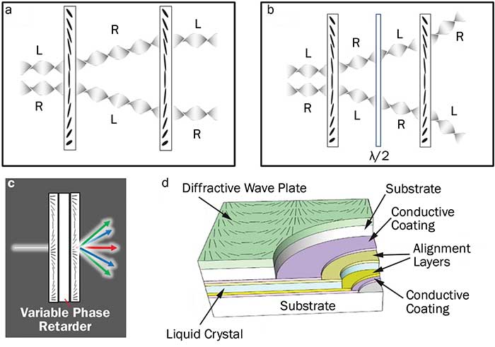
Figure 4. Switching of diffractive wave plate function using a variable phase retarder. Two identical diffractive wave plates in series with no intermediate phase retardation (a). The pair of diffractive wave plates comprising an intermediate half-wave retarder (b). Diffraction of a broadband beam by the system with spectrally modified zero-order transmission (c). The integrated structure includes a variable phase retarder and a diffractive wave plate (d). Courtesy of Beam Co.
Thus, the output beam may remain as collimated as the input one, and the lateral distance between the beams (Figure 4a) can be negligibly small due to the thinness of individual components. Switching polarization handedness by a variable phase retarder allows the beams to be further diffracted by the second cycloidal diffractive wave plate (Figure 4b). In the case of spectrally broadband beams, the half-wave retardation condition can be produced for a narrow range of wavelengths allowing some of the spectral components of the beam to transmit through the system (Figure 4c).
A useful combination is one that integrates a diffractive wave plate, such as a cycloidal diffractive wave plate with a liquid crystal variable phase retarder (Figure 4d). In this case, the phase retarder serves as a substrate for the liquid crystal polymer diffractive wave plate. The system is essentially an elementary stage that can be further integrated with additional such stages for all electronic multi-angle steering of a light beam and/or focusing the beam into multiple positions. The number of steering points, focal points, topological charges or beam shapes grows as 2N where N is the number of stages (Figure 5).
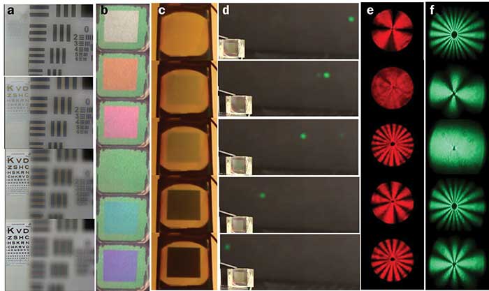
Figure 5. Switchable diffractive wave plate systems. Imaging with a diffractive wave plate lens switched between focusing and nonfocusing states (a). An electrically tunable filter (b) and a broadband variable transmission system (c) based on a variable phase retarder with liquid crystal polymer cycloidal diffractive wave plate overcoats — images correspond to an unpolarized white light input at various voltage settings. An all-electronic beam pointing with three stages of cycloidal diffractive wave plates paired with variable phase retarders (d). Visible and infrared light of various topological charges produced by a system of liquid crystal polymer vector vortex wave plates controlled with variable phase retarders (e, f). Courtesy of Beam Co.
Note the lack of chromatic effects due to a relatively large ƒ-number (~ 8) for an electrically switchable liquid crystal diffractive wave plate lens (Figure 5a). The first image is not visible, and the effect of the defocused light is revealed as a slight haze only.
Systems of variable phase retarders with liquid crystal polymer cycloidal diffractive wave plate overcoats allow various optical effects for an incident unpolarized white light (Figures 5b, 5c). Such devices act as a tunable filter or a broadband variable transmission system with no polarizers due to the variable phase retarder providing desired spectral modulation of the polarization state of the light at different voltage values.
An all-electronic beam steering device (Figure 5d) comprising multiple stages of liquid crystal polymer cycloidal diffractive wave plates and variable phase retarders is of particular interest due to large angle random access fast beam steering with no moving parts, and for large-area high-power laser beams. A generator of different topological charges for laser beams is just another example of numerous unique opportunities on the path to developing ultimately agile photonics systems (Figures 5e, 5f).
4G optics is of great value for infrared due to the transparency of liquid crystal materials for near-IR, mid-IR, and even longer IR wavelengths. Thus, any thin flat substrate for infrared optics is readily transformed into a thin-film lens, a prism or a beam shaper (Figure 6).
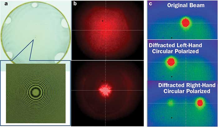
Figure 6. Diffractive wave plates for infrared, designed for and operating at 10.6-µm wavelength: A lens of ƒ-number approximately 1 showing expanded view of center region between crossed linear polarizers (a); defocusing and focusing of a laser beam when switching circular polarization handedness (b); pointing a cycloidal diffractive wave plate when switching the sign of circular polarization of the input infrared beam (c). Courtesy of Beam Co.
A glance into future
The word “liquid” in “liquid crystals” may create an impression of something fragile or unstable. The properties of liquid crystal polymers are nearly unaffected by temperature; due to the achievements of liquid crystal display industry, the operation range of many liquid crystals spans from -40 °C to over 100 °C. What is compromised at low temperatures is the switching speed.
Therefore, many applications are on the horizon, among the most exciting being the prospect of very large ultralight lenses for space telescopes, deep space communications, solar concentration and, here on Earth, ophthalmic lenses, including intraocular ones, with adaptive multipoint focusing capability. The 4G lenses and prisms may likely define the future of virtual reality and displays. For photonics, electrically switchable 4G optical components make feasible the fastest switchable lenses with the largest change in focusing power; all-electronic large-angle beam steering with thin and compact systems of low-power consumption; and generating beams of record-high topological charge for next-generation ultrafast optical communication, to name a few.
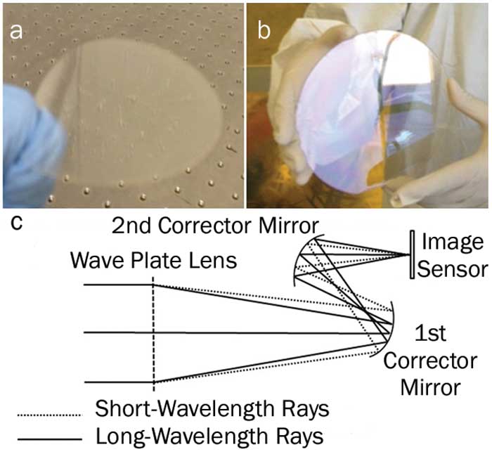
Figure 7. Preparing for the future: fabricating diffractive wave plates on plastic substrates (a); testing large area component technology using a 6-in. diameter diffractive wave plate lens on glass substrate (b); design concept of a space telescope of 20-m diameter with a primary diffractive wave plate lens — a system of small aspheric corrector mirrors with diffractive wave plate coatings allows diffraction-limited imaging in a wide spectral bandwidth (c). Courtesy of Beam Co.
The seeds of those future applications are being planted now with concepts in development for polarization-insensitive imaging systems, with demonstrations of diffractive wave plates on flexible polymer films (Figure 7a); with technology tests for very large optics (Figure 7b); designs of large broadband imaging systems (Figure 7c); adapting material basis for using advanced production techniques such as inkjet printing; and laying grounds for fabrication of large space optics where it belongs: in space7!
Meet the authors
Nelson Tabiryan, a pioneer in liquid crystal photonics developments, OSA Fellow, is the CEO and president of Beam Co., founded in 1996; email: [email protected].
David Roberts is chief systems engineer of Beam Co. His expertise includes IRCM, lidar, laser targeting, designation, rangefinding and SWIR and MWIR active imaging systems; email: [email protected].
Diane Steeves is the team leader of the Nanomaterials Science Team at the U.S. Army Natick Soldier RD&E Center. Her research interests include nanomaterials for sensor and eye protection applications; email: [email protected].
Brian R. Kimball is a research physicist at the U.S. Army Natick Soldier RD&E Center with interests in the interaction of light with nanophotonic structures; email: [email protected].
References
1. N. V. Tabiryan et al. (2010). The promise of diffractive wave plates. Optics and Photonics News, pp. 40-45.
2. S. Nersisyan et al. (2009). Optical axis gratings in liquid crystals and their use for polarization insensitive optical switching. J Nonlinear Opt Phys Mater, Vol. 18, Issue 1, pp. 1-47.
3. N. Tabiryan et al. (2015). Thin wave plate lenses of switchable focal length — new generation in optics. Opt Express, Vol. 23, Issue 20, pp. 25783-25794.
4. N. Tabiryan et al. (2016). Broadband wave plate lenses. Opt Express, Vol. 24, Issue 7, pp. 7091-7102.
5. L. Nikolova and P. Ramanujam (2009). Polarization Holography. Cambridge University Press.
6. L. De Sio et al. (2016). Digital polarization holography advancing geometrical phase optics. Opt Express, Vol. 24, Issue 16, pp. 18297-18306.
7. N. Tabiryan et al. (2016). Superlens in the skies: liquid-crystal-polymer technology for telescopes. SPIE Newsroom, DOI: 10.1117/2.1201601.006317.