
Nanometer-Scale Automation for Optical Device Manufacturing
Applying nanometer technologies to mass production requires attention to tolerance, environment, and equipment capabilities.
RJ HARDT, AEROTECH INC.
Manufacturers of optical devices know the importance of mature industrialized processes built around the cost savings of automation. These processes have made manufacturing optical devices economical in a number of speed- and bandwidth-sensitive markets, such as data communications, telecommunications, and commercial sensing. The technology that goes into these devices is constantly evolving to meet the future needs of these markets, which forces product manufacturing practices to follow suit.
Disruptive technologies, such as the advancement of chip-level optical functions and the miniaturization of device interconnections, have led to the adoption of new and unproven manufacturing processes in mass production environments. Component assembly and alignment tolerances that were once measured in tens of micrometers are now scrutinized in terms of nanometers. For example, chip-based photonics are commonly designed with waveguides that are only a few hundred nanometers wide and have alignment tolerances to external components or fibers that can be tens of nanometers. Not achieving these tolerances during the assembly process causes attenuation and signal loss that affect device functionality.
Optical research laboratories have made many process advancements at the nanometer scale, but taking these same techniques and applying them to an industrial automation process is no small task and carries significant risks. Fortunately, the risks of developing production platforms with enough robustness and throughput can be mitigated with the appropriate automation equipment.
Nanometer-scale manufacturing
Processes such as optical alignment, component placement, and automated test pose new hurdles on a nanometer scale because external influences are more pronounced than at the micrometer level. The finite mechanical rigidity of automation hardware, tight coordination requirements between automation and process tools, and electrical noise induced by the various control system components all exacerbate parasitic errors. Furthermore, a production environment will induce more environmental challenges that are not seen in an ideal lab setting; vibration from coexisting machinery, temperature variation, and harsh machine throughput requirements are exponentially more difficult to negate on the nanometer scale.
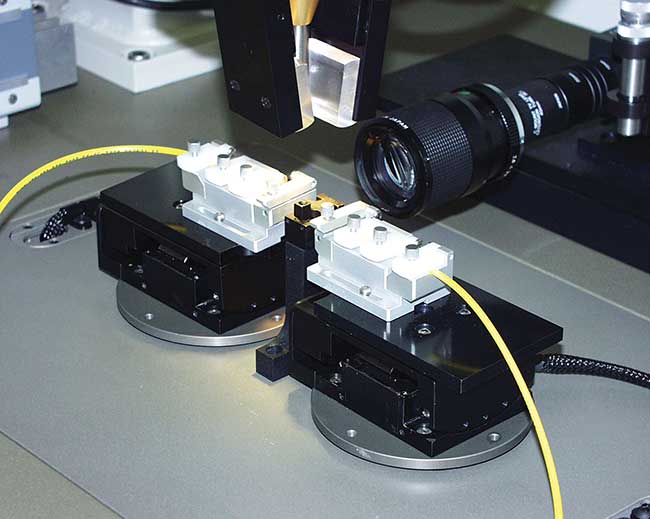
Vision systems can sometimes replace active tools, such as power meters. Courtesy of Aerotech.
The current high-volume manufacturing ecosystem is limited by the scale at which it can operate. Moving to a nanometer assembly scale requires pinpoint automation determinism and control capabilities that much of the current optical device manufacturing space has not yet mastered. The challenges are abundant, but strides are being made.
Laboratory processes and industry
Automation technologies suitable for assembling nanoscale optical devices in a laboratory setting are plentiful, and R&D process engineers can select from a wide variety of automation equipment. Although many of these technologies have flaws when moved to an industrial atmosphere, for laboratory qualifications they will perform as expected. From a component-positioning-equipment perspective, servo, stepper, or piezoelectric technologies are all acceptable choices for high-precision component alignment and placement. For example, highly flexible, six-degree-of-freedom, servo-driven hexapods are capable of 20-nm incremental motions and high-accuracy, multiaxis positioning. Alternately, piezoelectric actuators can also make incredibly small moves with extremely fast settling times (Figure 1).
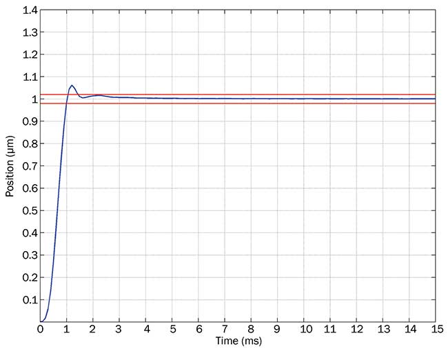
Figure 1. A plot showcasing a QNP-L linear piezo-actuated stage performing a 1-µm move and settling to ±10 nm in less than 2 ms. Courtesy of Aerotech.
Ultimately, the purpose of automation in a laboratory is to prove a process can be useful to the manufacturing of optical devices in higher quantities, which in turn promotes economy-of-scale cost savings. With this in mind, it is important for automation technologies at the R&D level to be suitable for production environments, which require robust manufacturing equipment and algorithms that can withstand physical disturbances and operator errors. Furthermore, the automation equipment selected must satisfy capital equipment cost drivers such as throughput, lifetime, and maintenance. There are trade-offs behind each automation technology applied to optical device manufacturing. The following sections offer general guidelines for selecting the appropriate equipment.
Robustness
Robustness in an automation system is the ability of the mechanical hardware and associated control system to withstand external influences, such as mechanical wear and electrical noise, over time. There are ways to specify a robust platform, but there are also many potential pitfalls. For example, choosing a contact screw or gear-based positioning actuator increases the chance of wear and reduces the chances of nanometer-level positioning over time. Another potential pitfall is a control system that induces electrical noise, which may contaminate the signals from process equipment, such as optical power meters.
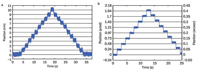
Figure 2. A plot showing a linear servomotor mechanical stage making single-nanometer motions (a); a plot showing a rotational direct-drive stage making 0.05 arcsec incremental motions (b). Courtesy of Aerotech.
One ideal solution for robustness is to use a direct-drive, noncontact motor coupled with a low-noise amplifier. These motors have no contact points that induce wear, and the low-noise, linear amplifier removes harmful electrical switching noises associated with common servomotor pulse-width modulation methods. These types of systems are capable of achieving long-term, nanometer-level linear and rotational alignment tolerances (Figure 2 a, b).
Another solution is to add stabilizing mass and stiffening mechanisms to the manufacturing station in order to reject the external influences and disturbances from the process equipment and environment. This can be done to any automation platform by characterizing the weak points of the mechanical design and optimizing for increased stiffness (Figure 3).
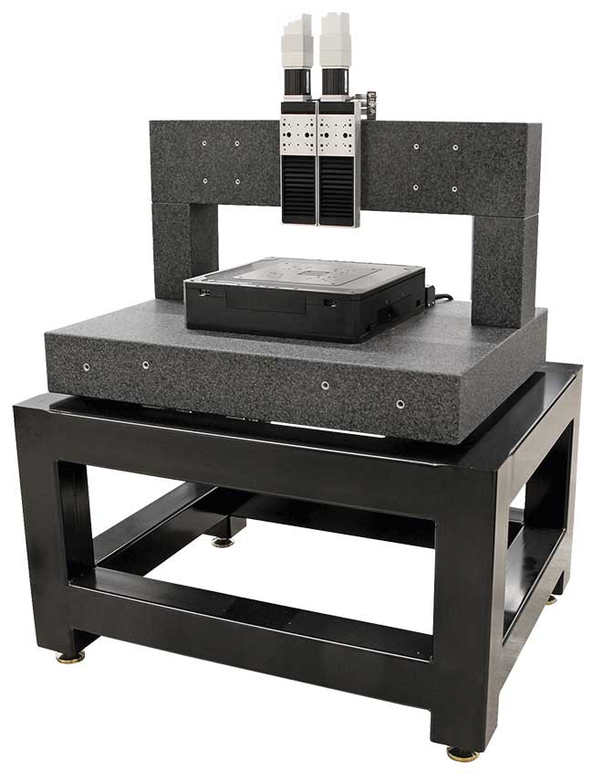
Figure 3. An example of using granite and a machine base to add stabilizing mass and increase stiffness, respectively. Courtesy of Aerotech.
Upfront equipment cost is always a concern, but an automation platform’s robustness can significantly reduce the overall cost of ownership of the machine and should be taken into consideration for upfront budgeting. Incorporating noncontact servomotors reduces the need for extensive maintenance or replacement after the automation platform has aged. This allows the same equipment to be
reused to automate the assembly of multiple optical device generations.
An example of a platform with limited robustness would be piezoelectric stepping actuators with strain-gauge feedback. They are often selected because of their reduced cost and footprint, but the long-term costs can be significantly higher than other technologies. They are prone to shorter life in industrial settings from the contact wear of the stepping mechanism and fatigue wear of the strain gage sensor, and may need to be replaced frequently. Ultimately, this makes long-term use difficult, and utilizing other available technologies with a higher upfront cost, such as servomotors or flexure-based piezo actuators, becomes more attractive.
Throughput
The cost of manufacturing an optical device can often be reduced by increasing the throughput of a machine. However, increasing process dynamics while operating on a nanometer scale is no easy task. First, selecting the right mechanical hardware will have a substantial effect on achievable system dynamics. Second, the process equipment must be tightly tied to the automated positioning equipment in order for the manufacturing platform to make quick and informed decisions. Optical power detectors and other tools are used to make process decisions, and any associated latency between these devices and the automation tasks will increase the time it takes to manufacture an optical device.
For high-dynamic, nanometer-level applications, piezoelectric and direct-drive servomotor platforms are ideal mechanical components. They utilize more bandwidth from the control system than other technologies, such as screw- or gear-driven systems. Ultimately, this leads to reduced motion-profile execution times and higher machine throughput. Furthermore, selecting a control system that allows for the direct integration of high-speed process tools into the automation algorithms is paramount.
Coordinating the position of the parts being assembled with the output from the various process devices needs to be done with as little latency as possible. Here, built-in, firmware-level alignment and data collection algorithms reduce the time for a process to complete. Figure 4 shows an ideal control network for the coordination of process tools and automation equipment with an emphasis on throughput.
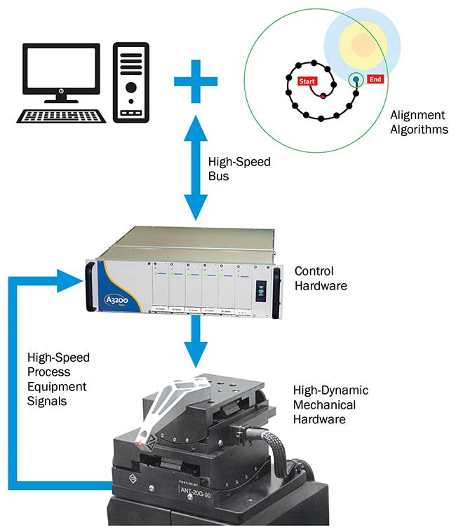
Figure 4. Schematic of an industrial machine controller and associated hardware. This system coordinates high-speed signals from optical process equipment with high-precision positioning devices. Courtesy of Aerotech.
Another potential avenue to increasing the process throughput is removing some of the active process tools inside a manufacturing station. This can occasionally be done by using position-registering cameras in place of active tools, such as power meters.
Although the use of cameras can be tricky on a nanometer scale, if the camera has enough resolution, and the positioning platform and tooling have enough precision, the various automation processes can be executed passively without process tool latency. This brings down the alignment and assembly time per component and can lead to overall faster throughput and lower device cost. Before switching to passive alignment techniques, it is important to understand what level of insertion loss (as expressed in decibels) is acceptable for the optical device because passive techniques are less precise than active techniques in many cases.
As optical devices continue to pave the way for product innovations in a number of different industries, it will be important to address the manufacturing concerns in a timely manner. Bringing new devices to market faster and in higher volumes will be important to the growth of the optical device market as a whole. Companies that can incorporate a production mentality into their R&D efforts will have a head start on their competition. Additionally, prioritizing an automation system’s robustness and throughput will help guide the selection of the appropriate equipment. Each has its place in determining performance on a nanoscale level for the next generation of optical device manufacturing processes.
Meet the author
RJ Hardt is a mechanical engineer and business development manager for Aerotech Inc., where he focuses on the optics and photonics sector. He has expertise in motion control and automation; [email protected].
/Buyers_Guide/Aerotech_Inc/c383