Microstructured optical fibers rely on the characteristics of photonic crystals to guide light. Practical applications for these unique fibers are emerging.
Dr. Wolfgang Mannstadt, Dr. Bernd Drapp, Bernd Hoppe and
Dr. Dirk Sprenger, Schott AG
For almost 40 years, glass fibers have guided and transmitted light, providing optical solutions in many fields of technology. During the past decade, a new variety of optical fiber, microstructured fiber, has emerged from the laboratory and is finding applications where conventional fiber either cannot be used or performs with far less efficiency.
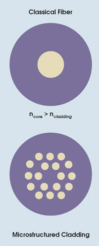
Figure 1. Classical optical fiber consists of a core and a cladding whose different refractive indices confine light in the core by total internal reflection (top). The cladding of photonic crystal fiber is a microstructure of glass and airholes (bottom).
Conventional optical fiber consists of a glass core surrounded by a cladding made of another type of glass or an organic polymer (acrylate) (Figure 1). The diameter of the core ranges from 5 to 120 μm, and the diameter of the fiber (both core and cladding) typically is 125 μm or more. The refractive index of the core is greater than that of the cladding, and light is guided in the core by total internal reflection.
At first glance, a microstructured fiber looks no different from a conventional optical fiber. Both consist of a core and a cladding. Only when viewed under the microscope do their differences become apparent (Figure 2). In the cladding of a microstructured fiber, there is a periodic alignment of holes that are approximately 1 μm in diameter. These are grouped around either a solid glass core or a large, hollow space. The two structures represent two types of microstructured fiber, which differ in principle and in application.
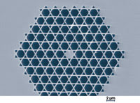
Figure 2. A scanning electron microscope image shows the microstructured glass cladding of photonic crystal fiber.
Microstructured fibers are made by first assembling 100 or so hollow glass tubes around a thin glass rod to create a preform (Figure 3). In the case of a hollow-core fiber, the core results from the absence of one or more tubes at the center of the preform. The preform then is placed at the top of a drawing tower, where it is heated until it softens and flows into the tiny fiber (Figures 4 and 5). If the drawing is performed properly, the fiber retains the geometry of the preform.
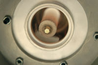
Figure 3. The photonic crystal fiber preform, shown here in the furnace of a drawing tower, is a regular assemblage of about 100 hollow tubes surrounding a single solid rod.
The first type of microstructured fiber, sometimes called photonic crystal fiber, has a cladding whose average refractive index (taking into account both the cladding material and the holes) is less than that of the core. Thus, light is guided in the core by total internal reflection, just as in a conventional fiber. However, a photonic crystal fiber differs from a conventional fiber in that many of its optical properties — e.g., dispersion and birefringence — may be engineered by properly designing the pattern of the holes.

Figure 4. The preform is heated at the top of a drawing tower and allowed to soften and flow into a thin fiber while retaining the geometry of the preform.
The second type, sometimes called photonic bandgap fiber, depends not on classical total internal reflection to guide light in the core, but on a photonic bandgap. The principle of a photonic bandgap is analogous to that of the electronic bandgap in semiconductors made of silicon or germanium. Inside a semiconductor crystal, only those electrons with a specific range of energies are allowed. These permitted energy bands are separated from each other by a so-called bandgap, or forbidden zone, so that electrons with energy values that lie within that zone are unable to propagate in the crystal. Similarly, there are photonic bandgaps in optical semiconductors; i.e., photonic crystals. In both cases, the bandgap exists as a result of the periodicity of the material structure.
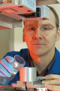
Figure 5. After the fiber has been drawn down from its preform, an acrylate is applied for protection. The acrylate is subsequently cured by exposure to ultraviolet light.
An optical semiconductor with a photonic bandgap in the visible range of the spectrum would be useless as a lightguide, of course. It would be unable to transmit visible light. The trick is to perturb the periodic microstructure by adding a core that consists of either air or glass. Such a local perturbation corresponds to the doping of electronic semiconductors in that it creates new allowed states within the bandgap. In photonic bandgap fiber, the core creates new state(s) by breaking the translation symmetry of the microstructure. As a result, light with a frequency that perfectly matches a new state can propagate along the perturbation.
For the light that is coupled into the fibers, the photonic bandgap represents a hostile desert. Only the energy level in the middle of the bandgap offers a chance for existence. Therefore, light of the appropriate frequency can exist only in the central core. It is unable to penetrate other areas of the cross section of the fiber or to escape. The only possibility for the light wave is to move along the fiber’s core.
Applications
The characteristics of the light that emerges from photonic crystal fiber can be manipulated by the fiber design, which involves both the materials selected and the geometry of the airholes. For example, because the fiber’s dispersion can be controlled, nonlinear processes in the core can be maximized or minimized (Figure 6). If the wavelength of the zero dispersion of the fiber is set close to the propagating wavelength, phase matching is greatly facilitated.
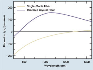
Figure 6. The dispersion characteristics of photonic crystal fiber can be manipulated by designing the microstructure appropriately. In this case, the zero-dispersion wavelength was set to ~750 nm, far lower than the ~1300-nm zero-dispersion wavelength of typical single-mode fiber.
If monochromatic light from a laser were coupled into such fiber, a supercontinuum — light with a relatively flat frequency spectrum that spans as much as an octave — could be generated. In this manner, these novel fibers combine the new concept of photonic structures with highly nonlinear processes to produce previously inaccessible quantum optical effects. This represents a totally new type of light source that would be excellent for use in medical applications such as optical coherence tomography.
Photonic bandgap fiber is interesting for a number of reasons, not the least of which is its ability to guide light in an air core. As mentioned, the light wave can be transmitted in photonic bandgap fiber through a core that consists of air. This is impossible with traditional optical fiber because the light guiding is based on total internal reflection, so the refractive index of the core must be greater than that of the cladding. There is no material with an index less than unity, the index of air.
Benefits of an air core
Air-core fiber offers interesting possibilities. In conventional fiber, light is attenuated as it propagates along the glass core because of optical absorption, and different light frequencies move at different velocities because the glass is dispersive. Dispersion causes pulses — which consist of many frequency components — to broaden as they travel along the fiber. Both optical absorption and dispersion can be practically eliminated in air-core fiber. And the deleterious nonlinear effects that occur in glass-core fiber are not an issue in fiber with an air core.
Air-core photonic bandgap fiber can transmit a much higher intensity of light than glass-core fiber. At the same time, it has a significantly higher life span because it experiences a lower thermal load. Air absorbs less light than glass does and, as a result, is heated less by light, so a possible application for this type of microstructured fiber would be guiding high-intensity light in laser welding and laser cutting.
Meet the authors
Dr. Wolfgang Mannstadt is a physicist in the materials development group at Schott AG in Mainz, Germany; e-mail: [email protected]om. Dr. Bernd Drapp is with the R&D new business team, Bernd Hoppe is a development engineer in the R&D department, and Dr. Dirk Sprenger is manager of the materials development group within R&D, all at Schott in Mainz.