Tony Amarel and William Gornall, Exfo Burleigh Products Group Inc.
Fiber Bragg gratings, which have had such success in wavelength division multiplexing for telecommunications, also have been adapted to environmental sensors. These sensors measure parameters such as temperature, pressure and strain, which cause shifts in the peak of the spectrum reflected from the grating. Because the required information from a fiber Bragg grating sensor is carried with the wavelength of the reflected optical signal, the method of measuring the absolute wavelength is a critical part of a fiber optic sensing system.
One approach to determining the precise peak wavelength in the grating’s reflected spectrum is to use an amplified spontaneous emission broadband source combined with a Michelson interferometer optical spectrum analyzer. This method, while not laser-based, does provide accurate measurements of the reflected wavelengths. This method is most important in monitoring applications where reliable sensor measurements must be made over a long period under varying environmental conditions without recalibrating the instrument.
Michelson interferometry, combined with fast Fourier transform digital processing, has been used for many years in wavelength meters to accurately determine the wavelength of laser sources. It also can be applied as an optical spectrum analyzer (Figure 1). It is well-known that the advantage of the interferometer wavelength meter over other types of optical spectrum analyzers is its high absolute wavelength accuracy and reliable repeatability under all conditions.
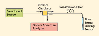
Figure 1. One method of measuring the wavelength reflected from a fiber Bragg grating is to send light from a broadband source down the fiber and to analyze the reflected spectrum.
Wavelength meters use a special Michelson interferometer design (Figure 2). An incident beam splits between a fixed path and a path that can be changed by a moving end reflector. The end reflectors in both paths are corner-cube retroreflectors that displace the returned beams. Beams of a single wavelength recombined at the beamsplitter produce a sinusoidal intensity variation at the detector as the moving reflector changes the optical path difference. This signal goes through one complete cycle of intensity maximum and minimum, known as an interference fringe, when the optical path difference changes by one wavelength of the incident light.
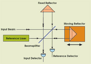
Figure 2. A Michelson interferometer designed for wavelength measurement includes a reference laser with a known wavelength that calibrates every scan of the interferometer.
The advantage of the displaced paths in this Michelson interferometer is that a second beam from a reference laser with a known wavelength can be introduced along exactly the same path in the opposite direction, so that its fringe signal is picked up by a separate detector. This reference signal is used to accurately calibrate the scan of the interferometer and to determine the absolute wavelengths in the spectrum of the input light.
The interference fringe pattern generated by the interferometer input detector will have a waveform that represents the frequency components of the optical input signal. For example, light reflected from a single fiber Bragg grating will produce a simple sinusoidal signal. The signal from multiple fiber Bragg gratings reflecting different wavelengths will result in a much more complicated interference fringe pattern. However, regardless of the complexity of the pattern, the optical frequency spectrum can be derived from a fast Fourier transformation analysis, and the wavelength of each peak can be accurately determined based upon the known wavelength of the reference laser.
Illumination source
The fiber Bragg grating measurement system also requires a broadband illumination source to “light” the sensor. A good choice is an amplified spontaneous emission source that has high output power and that provides sufficient reflected signal, even from sensors with very low reflectivity (Figure 3). The emission source outputs a broad spectrum — more than 100 nm, in some cases — to allow illumination of many sensors on one fiber optic line.
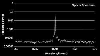
Figure 3. A typical spectrum from a 7 percent reflectivity fiber Bragg grating sensor shows excellent signal-to-noise ratio for precise wavelength determination.
One concern with an amplified spontaneous emission source is that its spectral shape could distort the returned fiber Bragg grating spectral peak and affect the wavelength measurement. This problem is easily overcome by recording the shape of the emission source and using it to normalize the grating’s reflected spectrum. This guarantees the correct wavelength measurement from the sensor.
A fiber Bragg grating interrogation instrument designed for field use includes the Michelson interferometer spectrum analyzer and amplified spontaneous emission broadband source with full electronics in one chassis. Only the fiber optic cable connecting multiple sensors needs to be attached externally.
One instrument can easily service several fiber lines to different locations with the addition of an optical switch to the system that cycles the connection of each line to the instrument.
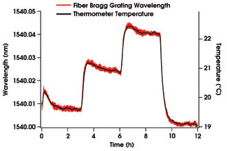
Figure 4. Measurements of the wavelength reflected from the fiber Bragg grating sensor accurately match the thermometer temperature as the ambient temperature of a water bath is cycled in steps over several degrees Celsius. The two traces show that the wavelength measured by the sensor follows the thermometer measurement with a precision of ±0.1 °C.
An important requirement for any fiber Bragg grating measurement system deployed for field applications such as oil well or geophysical monitoring is that the measurement accuracy not be affected by variations in the ambient environment. Tests have shown that the technique accurately measures temperature (Figure 4) without being affected by changes in the instrument temperature (Figure 5).
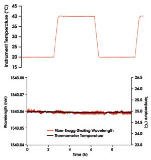
Figure 5. Both the Michelson interferometer-based fiber Bragg grating interrogator and an electronic thermometer were maintained in the same water bath at constant temperature. The temperature of the instrument was cycled slowly between 20 and 40 °C, as shown on the upper trace. The two lower traces show that the wavelength measured by the sensor remains constant, unaffected by the change in the instrument temperature.
Conclusion
Many applications today require remote sensing of local environmental conditions. Fiber optic systems incorporating fiber Bragg grating sensors that perform sensing and transmit the data provide high-accuracy absolute wavelength-encoded measurement, independent of the source power level. The advantages of incorporating fiber sensors into many remote sensing applications are being realized.
A Michelson interferometer optical spectrum analyzer combined with an amplified spontaneous emission broadband source provides a very accurate and repeatable wavelength measurement of the spectrum reflected from a sensor. It also has been demonstrated that a well-designed instrument can make accurate wavelength measurements independent of wide variations in its operating temperature measurements.
Acknowledgments
The authors would like to thank Mike Houk for consultation and for providing the fiber Bragg grating temperature.
Meet the authors
Tony Amarel is a product line manager and William Gornall a director of technology at Exfo Burleigh Products Group Inc. in Victor, N.Y.