Christopher L. Cromer, National Institute of Standards and Technology
The National Institute of Standards and Technology (NIST) has been tasked by the Defense Advanced Research Projects Agency with providing wall-plug efficiency and spectral measurements of high-power, high-efficiency laser diodes and arrays as part of its Super High Efficiency Diode Sources (SHEDS) program. These optical sources present a significant measurement challenge. Edge emitters have a high divergence on the fast axis, which makes it difficult to capture the entire beam. Moreover, the high power levels and the relatively large size of the arrays can challenge the best commercially available optical radiometers.
Measurements of laser power commonly use thermopile-based or integrating-sphere radiometers, but these instruments have shortcomings when applied to the diode lasers and arrays we are dealing with here. To capture the multiple beams from the diode array, the radiometer must be very close to the array. Unfortunately, with large-area disk-type radiometers, this can disrupt the thermal equilibrium of the absorber disk, which distorts the temperature measured with the thermopile. In addition, most high-power detector coatings reflect a significant portion of the incoming radiation, but instead of being lost, this radiation can be reflected back to the detector by hardware near the radiometer.
On the other hand, integrating-sphere-based radiometers are notoriously sensitive to port conditions. Again, because the laser diode or diode array being measured must be placed directly in the input port, significant errors can occur. Additionally, baffle design and thermal effects can influence the accuracy of sphere measurements, especially for high-power, highly diverging sources.

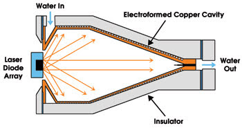
Figure 1. The laser diode array is placed in the entrance aperture, and the cavity absorbs nearly 2π sr of the array’s optical output. Water flows through channels in the outer surface of the cavity, and the laser power is inferred by measuring the temperature rise of the water.
To avoid these problems, we are developing an optical radiometer that is based on measuring the temperature increase of the water that cools the device (Figure 1). A copper cavity with a black coating on the inside captures and converts the laser output to heat. The cavity is cooled with water flowing through channels on the outer surface of the copper.
Electrical heater
The power measurement is then provided by the equation P = ρm · ΔT · Cp, where ρm is the mass flow, ΔT is the difference in temperature between the input and the output water, and Cp is the heat capacity of the water. Measurements down to a few watts are possible with calibrated thermistors and a high-accuracy (Coriolis type) mass-flow meter. The effective heat capacity can be measured by introducing an electrical heater into the water flow and measuring both the water flow and the temperature increase ΔT of the heater, making the optical measurements traceable to electrical standards.
This class of detector loses very little heat to the environment. The ΔT value is typically less than 1 °C, and more than 99 percent of the heat absorbed by the cavity is transferred to the water. The cavity also absorbs 99.9 percent of the optical radiation, so very little reflects onto the laser array.
The coating on the inner surface of the cavity is a metallic nickel-phosphorus black absorber that has a high damage threshold and very low reflectance. This same coating was employed in the Total Irradiance Monitor placed onboard the recent NASA Solar Radiation and Climate Experiment satellite to monitor solar irradiance. The coating was chosen for its durability and very high absorption.

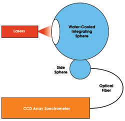
Figure 2. The lasers’ spectral characteristics are measured with a double-integrating-sphere system.
The spectral measurements are performed using a fiber-coupled CCD array spectrometer and a water-cooled, gold integrating-sphere system. The sphere system comprises a 25-cm water-cooled sphere and a side-mounted 10-cm sphere (Figure 2). This double-sphere configuration ensures adequate spatial integration of the laser array output. The spectrum of each individual laser in an array is coupled into the system with magnifying optics.
Steady-state electrical measurements are accomplished with the usual high-current shunt and voltmeter. Pulses will be measured with a commercial power analyzer, which can be calibrated at NIST for the appropriate experimental conditions. Subject to further evaluation, we believe that the error sources combined should result in an uncertainty for the efficiency measurements of less than 2 percent.
If demand is sufficient at the conclusion of the SHEDS project, we intend to continue offering the technique through NIST Calibration Services in Gaithersburg, Md., for optical radiation measurements, available to anyone for a fee.
Meet the author
Christopher L. Cromer is a physicist at the National Institute of Standards and Technology in Boulder, Colo.; e-mail: [email protected].