Maximizing Optical Alignment
Serial positioning architectures offer unprecedented alignment precision, but where space constraints exist, parallel-kinematic designs fit the bill.
RJ HARDT, AEROTECH INC.
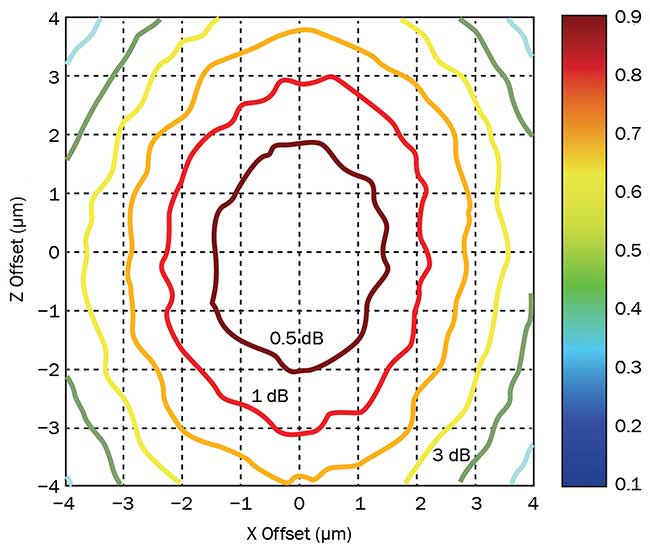
Advances in silicon photonics and micro-optic technologies are driving automated alignment tolerances down to nanometer levels. Misalignment between optical components in today’s photonic devices directly impacts the quality of light transmission. And misalignment by only a few micrometers can result in final device power losses of 50 percent or more (Figure 1). Photonic device manufacturers are rushing to develop new alignment techniques and hardware to keep up with spatial tolerance requirements between optical components. These spatial tolerances can be controlled during automated alignment by implementing the optimal positioning system architecture.

Figure 1. Power loss between an optical fiber and silicon chip from misalignment in 2D space. Courtesy of Aerotech Inc.
There are two types of architectures: serial kinematics and parallel kinematics. They differ in spatial configuration, programming and required hardware, and choosing the ideal architecture can be challenging. The guidelines that follow below shed light on the architectures available and factors to consider when implementing them.
Architecture choices
Serial positioning architectures use a single actuator, or motor, to position an optical component in one direction in space. These systems can be stacked on top of one another to achieve positioning requirements in all six degrees of 3D space (three linear and three rotational). Parallel positioning architectures use multiple actuators to position an optical component in one or more directions in space. They, too, can be configured to achieve positioning requirements in all six degrees of 3D space.
Each architecture enables the user to program in 3D space, and in addition, each allows for the selection and programming of a point in space about which rotations may be performed. This is useful for aligning arrays of components, such as a fiber block of multiple incoming fibers to a chip with multiple waveguides. There are limitations in terms of achievable precision between the two kinematic approaches, especially at the point of interest where the alignment process is being executed.

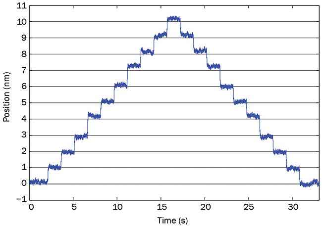
Figure 2. Positional step sizes as small as a single nanometer can be achieved by using a serial linear positioner. Courtesy of Aerotech Inc.
In general, the highest level of alignment precision can be achieved with a serial design because serial systems provide the following:
• Better positional accuracy at the work point where the component being aligned is held.
• Smaller incremental step sizes in each direction of motion (Figure 2).
• Better repeatability when returning to previous positions.
Serial systems exhibit these advantages because they limit the number of actuators moving at any given time. For example, in the parallel hexapod system (Figure 3), all six actuators move at the same time to move the payload in a single direction of motion. This means that error motions from the individual actuators are compounded. A serial system simplifies the motion requirements since each axis moves independently of the others and only does so when needed. This allows serial systems to align optical components with less motion-induced error.

Figure 3. An example of a six-degree-of-freedom (DOF) serial motion platform in the form of stacked single axes of mechanics (left), and a six-DOF parallel-kinematic platform in the form of a hexapod (right). Each red arrow indicates the direction of motion for the actuator. Courtesy of Aerotech Inc.
Furthermore, the joints required by parallel-kinematic systems add motion-related error caused by mechanical compliance. Serializing the motion eliminates these additional joints and leads to serial devices capable of individual motions, or step sizes, of less than 10 nm while providing travels of hundreds of millimeters. This long travel is useful for ancillary processes, such as part loading and tool changing.
Other notable advantages of serial platforms are increased design modularity and simplified programming. The axes can be separated, reducing the working height while still allowing the user to program in all six degrees of freedom (DOF). This flexibility is often lost with parallel-kinematic systems because of the need for mechanical linkages between the actuators. Additionally, the linkages between parallel-kinematic actuators require transformational code to be written into the motion controller so the user can program in familiar coordinates (e.g., Cartesian space). These transformations make simple operations such as finding home references for each axis very difficult. Serial architecture eliminates the need for these more complex transformations.
Parallel-kinematic architectures
Parallel-kinematic designs generally cannot achieve the positioning precision of serial designs. However, they are better suited for use in some cases. Primarily, if the physical footprint of the alignment station is of concern or there is limited space to add motion control, parallel-kinematic approaches can help. The actuators do not have to be stacked on one another as with serial systems and can be placed much closer to each other. This means the footprint of the motion system can be reduced up to 50 percent in the vertical direction. Another advantage of a parallel architecture is the freedom to place actuators where needed to improve stiffness and rigidity. If designed correctly, multiple actuators can share the burden of the payload simultaneously. This allows users to position heavier payloads without concern for positional stability while the components are bonded into place.
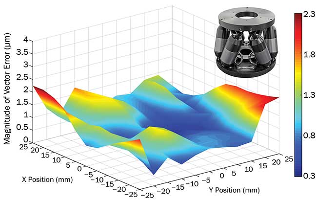
Although hexapods are generally not known for their high accuracy, new parallel-kinematic designs in some cases have positioning performance comparable to serial-kinematic systems. The 3D-vector-positioning accuracy of a hexapod when moved in an XY plane is shown in Figure 4. This level of performance can be attained using high-precision, robust mechanics and advanced control/calibration strategies.

Figure 4. A plot of the XY plane vector-positioning error using an Aerotech HEX300-230 six-axis hexapod. Courtesy of Aerotech Inc.
Since each positioning architecture has its own benefits for optical alignment systems, it makes the most sense to combine them where appropriate. Using serial architectures for high-precision processes and parallel architectures for reducing platform footprints and increasing load capacities maximizes the performance of the total alignment process. Therefore, it is then important to choose an automation supplier that can easily combine both serial and parallel architectures in a single package. This gives the designer more hardware tools to implement and offers the programmer a single platform with which to develop the application software.
Meet the author
RJ Hardt is a mechanical engineer and business development manager for Aerotech Inc., where he focuses on the optics and photonics sector. His expertise lies in motion control and automation; email: [email protected].
Hybrid Approach: When Space Is Tight, but Precision Is a Must
Because of the developing industrial supply chain for automated photonics alignment machines, users of these systems often require purpose-built platforms based on the optical components being aligned. This enables machine design flexibility, and it allows the machine builder to select automation and positioning systems that fit the exact needs of the application.
Consider a recent case in which a manufacturer required alignment between a semiconductor laser source, a microlens and an integrated waveguide on a photonic integrated circuit (PIC). In this scenario, multiple components had to be aligned simultaneously and precisely to one another to transmit a sufficient amount of light into the PIC. Each of these photonic components required multiple, small positional translations with respect to one another, and they also had to be translated in a space-constrained environment because of the limited accessible working volume. To further complicate the design, a high-speed automated parts loading step was also required.

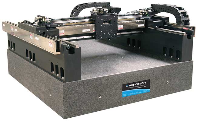
An Aerotech AGS15000 gantry used for overhead high-speed pick-and-place loading and unloading operations.
A combined serial and parallel-kinematic positioning system was used to address the multiple variables and constraints this application presented. A high-speed overhead gantry platform was implemented for the loading and unloading of optical components. Its throughput depended on a reduced and stiff payload, so a parallel-kinematic six-degree-of-freedom (DOF) hexapod was added between the gantry’s moving carriage and the part-gripping tools.
Finally, to enable the highest possible light transmission between the laser, lens and waveguide, a high-precision serial architecture system was placed on the base below the overhead gantry. This serial system was separated into two modules to allow the PIC and laser source to move independently, allowing enough working volume between the laser source and chip for the parallel-kinematic hexapod to manipulate the microlens into its optimal position. Ultimately, all components could be aligned simultaneously with sub-100-nm precision, which allowed for reduced transmission light loss supplied to the photonics chip.
The flexibility allowed the design team to choose the best positioning architectures that were available. After the machine was built, the ability to control and program the parallel-kinematic hexapod simultaneously with the two separate serial positioning systems and gantry was of great benefit. This functionality allowed the design and implementation teams to reduce the complexity of the control system and software development timeline, which eventually brought the product to market faster. When building an automated optical alignment station, both serial and parallel positioning architectures should be considered.
/Buyers_Guide/Aerotech_Inc/c383