Selecting the proper technology improves performance and enables designers to achieve smaller package size, extend component life and meet touch temperature standards in biomedical devices.
MICHAEL BUCCI, AAVID THERMACORE
Biophotonic devices, packages and systems are subject to performance variability and failures at high temperatures because of thermomechanical stresses and corrosive decay. But optical performance depends on consistent behavior of materials and components. Especially problematic are devices with high power densities that create hot spots, which can wreak havoc on performance. As a result, designers of biomedical lasers, high-powered LEDs and superluminescent diodes are evaluating thermal management solutions much earlier in the design process.
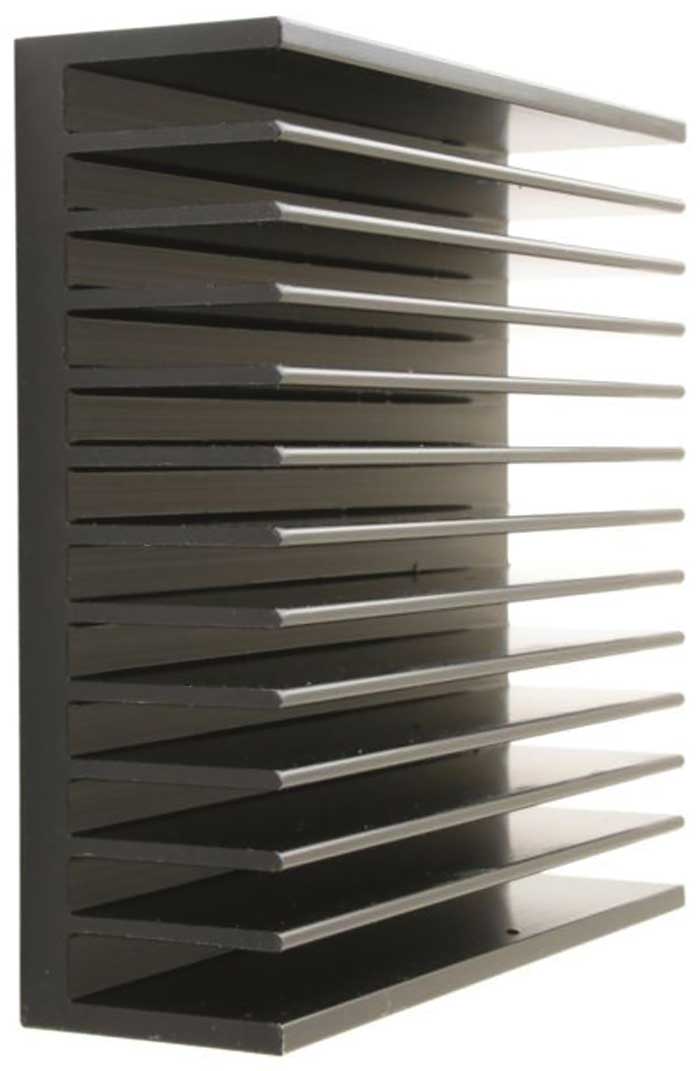
This example of an aluminum extrusion heat sink makes use of natural convection.
With proper thermal management, a designer can reduce size and weight, lower energy consumption and improve reliability and precision. Proper thermal management also can extend the operational life of the device and help designers meet temperature limits, including IEC 60601 touch temperatures. Biophotonic applications range from surgical and cosmetic lasers to imaging equipment and diagnostic instruments. Given this diversity, it is worthwhile to consider the advantages of different types of thermal management.
Today’s thermal challenges
Optical filters, collimators, laser diodes, detectors and other high heat-flux components produce concentrated heat loads that must be dissipated. Otherwise, as temperatures change, materials with different coefficients of thermal expansion (CTE) expand and contract at different rates, inducing mechanical stress on the assembly. As with most electronic parts, the operational life of optoelectronic components decreases with higher operating temperatures and can be expressed through the Arrhenius Equation.
Displacements caused by microscopic heat flux are associated with creep, stress deformations and material aging that will compromise the performance and longevity of the biophotonic device. Medical devices have additional thermal challenges. The IEC 60601 standard defines allowable “touch temperature” limits for medical devices that may contact patients or staff. Allowable temperatures can be as low as 43 °C for metals, with slightly higher temperatures allowed for less conductive materials, such as plastics.
Common thermal solutions for photonic devices range from all-metal heat sinks to more advanced technologies such as refractory metal vapor chambers and porous metal liquid cold plates. They also include thermal interface materials (TIMs), though TIMs are more of an accessory item used in conjunction with almost all thermal solutions.
Thermal interface materials
TIMs are often used between the mating components of the thermal system to ensure consistent contact and reliable heat transfer. The bond lines should be kept as thin as possible because these materials have poor thermal conductivities. However, voids can appear if the bond line is too thin, which can have a major impact on performance. TIMs come in many options, such as gap pads, greases, foils, phase change materials (PCMs), epoxies and solders.
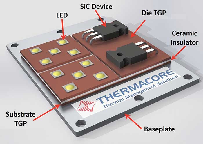
Refractory metals allow thermal ground planes (TGPs) to directly attach to electronic component dies.
Selecting the appropriate TIM usually depends on requirements associated with dimensional compliance, thermal conductivity, removability, electrical conductivity, chemical compatibility and the allowable attachment method.
Thermal solders are known to be the best performers; however, they can be challenging to work with, require high temperature exposure, and are intended for permanent attachment. These are followed by epoxies, which are easier to work with, although they have lower thermal conductivities and are also intended for permanent attachment. Thermal greases, or pastes, perform similarly to epoxy. Though they are messy and can eventually dry out, they allow for easy disassembly.
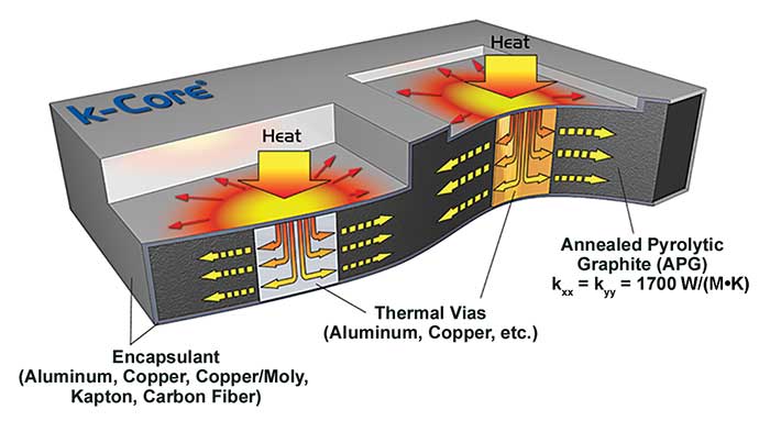
The conductivity of annealed pyrolytic graphite is four times that of copper at room temperature and six times copper at cryogenic temperatures. However, these high conductivities are only in X-Y directions. Aluminum or copper vias can be inserted below the heat source to send the heat into the graphite.
Gap pads and films are soft and offer the most compliance for the dimensional variations of mating parts. They typically have self-adhesive on one or both sides for easy attachment and replacement. The downside is that they tend to be thicker, which can lead to a higher thermal resistance. They can include ceramics, aluminum or graphite to increase thermal conductivity or to increase their operating temperature range. PCMs have lower conductivities. Once heated, they soften to better fill in gaps between mating components; once cooled, they form a light bond to mating components, but can still be removed fairly easily.
Heat sinks
A metallic heat sink transfers heat by conduction through a base to air side fins. By far the most common and economical heat sink material is aluminum, followed by copper. Heat-generating components are mounted to the base, while the air side fins release heat into the ambient air through natural convection or through forced convection using a fan.
Designers should consider optimizing the fin type, spacing and thickness in relation to the airflow rate. Depending on the level of performance needed, this may require computational fluid dynamics software. While optimization helps improve performance, it can also help designers meet noise limits, which is
typically 45 dBA for labs and health care facilities.
When heat loads are too concentrated, a basic heat sink will not be able to conduct heat uniformly across its base, resulting in nonuniform heat distribution on the air side fins. Uneven heat distribution makes the heat sink less efficient, because only a portion of the fins are convecting the heat efficiently.
Heat pipes and vapor chambers
There are several ways to improve heat spreading across the heat sink base to increase the air side fin area efficiency and effectiveness. The most common solution is to apply heat pipe technology.
Heat pipes are two-phase heat transfer devices that offer extremely high thermal conductivities. In its most simple form, a heat pipe consists of a vacuum tube with an internal wick structure along the length. A liquid is inserted into the vacuum tube. As heat is applied, the liquid absorbs it and vaporizes. The vapor spreads through the vacuum to cooler regions where it condenses into a liquid and releases the heat. The wick transports the liquid back to the heat source(s), and the cycle repeats perpetually.
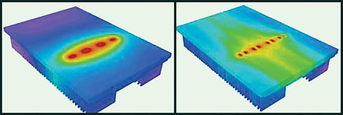
Thermal profiles show the superior conductivity of heat pipe heat sink (right) over an aluminum extrusion heat sink (left).
The extreme thermal conductivity of a heat pipe usually ranges between 10 and 1000 times that of copper — which has a thermal conductivity of 390 W/(m·K). Because heat pipes are passive with no moving parts, well-constructed heat pipes are extremely reliable. Many are still operational after decades of continuous use in the field, with minimal degradation in performance.
Heat pipes are most commonly used to cool high-power electronics with concentrated heat loads, although they are used in a wide variety of applications and are even used to heat components when necessary. Contrary to what their name implies, heat pipes can be fabricated into a variety of shapes and sizes. Heat pipes that are produced in planar forms are known as vapor chambers. Their flat form facilitates highly effective lateral heat spreading. Vapor chambers generally range in thickness from 0.75 to 4 mm.
The most common heat pipe formulation comprises a copper tube, a copper wick and water. But heat pipes can be made of different materials and with different working fluids to handle a wide range of operating conditions. For high temperatures, heat pipes can be constructed from refractory metal alloys, such as rhenium, molybdenum and tungsten, which can handle high temperatures that would melt copper in seconds. While conventional heat pipe technology can handle heat fluxes of up to 350 W/cm2 and vapor chambers can handle 700 W/cm2, refractory metal heat pipes can handle up to 127,000 W/cm2.
Refractory metals also have very low coefficients of thermal expansion, similar to silicon and ceramics. This enables refractory metal heat pipes, such as thermal ground planes, to directly attach to electronic component dies without the need for standard substrates that have very poor conductivities. Because refractory metals will expand and contract at the same rate, the assembly can maintain its structural integrity throughout the thermal cycle.
Heat pipes and vapor chambers are commonly integrated into the bases of heat sinks to improve heat spreading to the air side fins. They also can be used to transfer heat away from a heat source to a remote heat sink. In many cases, heat pipe technology improves performance enough to eliminate the need for fans.
Annealed pyrolytic graphite
A lightweight, highly conductive material, the conductivity of annealed pyrolytic graphite (APG) is four times that of copper at room temperature and six times copper at cryogenic temperatures. APG conductivity does not change with size, as opposed to pyrolytic graphite, whose conductivity decreases with thickness. With both materials, however, the high conductivities are only in X-Y directions. The conductivity in the Z direction is poor, but aluminum or copper vias can be inserted below the heat source, to send the heat into the graphite.
APG is constructed of carbon planes that are held together by weak van der Waals Forces, so they can delaminate very easily. For this reason, APG is almost always encapsulated in other materials, such as aluminum. It can be machined to different sizes and configurations.
APG is most appropriate for applications that either operate across a very wide temperature range, must send heat downward at cryogenic temperatures, or, most commonly, where weight must be reduced.
Liquid cold plates
Liquid cooling typically involves circulating a liquid through a plate and attaching the plate to the heat source. The liquid absorbs the heat, then circulates it to a point where the heat can be dissipated to the environment.
There are four primary types of liquid cold plates used in photonics applications:
• Tube-in-plate consists of tubes pressed into plates, usually in a serpentine pattern, to direct liquid flow through a larger surface area. This thermal management technique can be scaled to handle larger areas with comparatively low heat fluxes. The technology is generally something designers try first, because it tends to be low cost. It also offers lower performance levels.
• Brazed plate designs involve joining two plates containing grooves on the mating face, to form a single plate with internal grooves or channels for the liquid to pass through. This solution offers better performance over tube-in-plate technology, with less overall mass. It is especially useful for dissipating large heat loads across a wide area, although its heat flux capability is only slightly higher than tube-in-plate designs. Plates can be bonded by two methods. Controlled atmosphere brazing (CAB) bonds the components within a partially sealed furnace. The components are heated to a specific point for a set period of time. The flux material begins to melt along the mating edges of the components. The temperature is then reduced, and the components bond together as the flux hardens.
Vacuum brazing provides a stronger and more reliable bond than CAB, though it is a more time-consuming process. Instead of flux, a pre-cut foil of the same material as the components melts between the components to aid bonding. The assembly is heated under vacuum to prevent the introduction of impurities that weaken the bond lines. Vacuum brazing is primarily used for low-quantity builds, while CAB can meet the performance requirements for high-quantity builds.
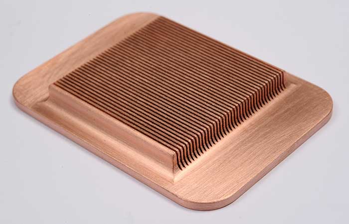
Microchannels increase the amount of surface that is in contact and can handle heat fluxes up to 1000 W/cm2. This option is well-suited for cooling very high-power density electrical and optical components.
• Microchannels incorporate channels with diameters as small as 0.2 mm into a plate, which increase the amount of surface area that is in contact with the flowing liquid, beyond what tube-in-a-plate and brazed thermal management technologies can offer. This enables microchannel technology to dissipate more heat in less space and can handle heat fluxes up to 1000 W/cm2. This option is better suited for cooling very high-power density electrical and optical components.
• Porous metal further increases the amount of surface in contact with the circulating liquid to maximize the heat exchange rate even further. With this technology, the liquid circulates through a porous metal media that is sintered into the plate, almost like a honeycomb pattern. This is an ideal solution when concentrated heat loads generate high heat fluxes and temperatures, such as with high-power laser diodes. Porous metal technology can be customized to accommodate heat fluxes over 5000 W/cm2.
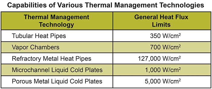
There are limits on general performance of each heat flux thermal technology (Table above), but the performance of each will vary in individual applications. When applying a thermal management solution, designers face trade-offs between size, weight, heat load, operational life, noise limits, thermal performance and cost. It is important to discuss the trade-offs with a thermal management specialist to determine the appropriate solution and the performance that can be expected.
Meet the author
Michael Bucci is the market development manager for Medical & Test Equipment in North America for Aavid Thermacore in Lancaster, Pa.; email: [email protected].