Customer demands are driving vendors to push the boundaries of machine vision technology, leading to faster, smarter and higher-resolution systems.
Hank Hogan, Contributing Editor
Northrop Grumman Corp., like any other defense contractor, needs to track parts throughout the production line and onward through subsequent use. That need is faced by automotive parts suppliers as well and is a nearly universal aspiration among all types of manufacturers. The solution mandated to contractors by the US Department of Defense is a two-dimensional matrix of dots that marks an item with a unique, specific and omnipresent identification code. That requirement, in turn, fuels a demand for specialized machine vision systems.
The advent of 2-D direct part mark identification is among several current trends in machine vision. Others include a push toward greater resolution and intelligence, and the incorporation of sight into robots.
Advances in direct part mark identification result from the convergence of demand and technology. On the demand side, the Defense Department has an active unique program — known as UID — that requires contractors to identify every mission-critical component valued above a certain level. The automotive and aerospace industries have their own part-ID plans. As a result, second-, third- and fourth-tier producers are beginning to need to brand parts themselves, noted David Wyatt, president of Midwest Integration in Mishawaka, Ind.
“They’re going to mark everything from cradle to grave,” he said of the efforts of Defense Department suppliers. He added that reading such identifiers is now the hottest area in machine vision.
On the technology side, laser and mechanical devices produce direct part marks that can survive manufacturing processes. However, there is a trade-off between marking and reading, as a better mark allows less sophisticated reader software and hardware to deliver good identification results. According to Peter Langworthy, senior program manager for Northrop Grumman’s Automatic Identification Technology Center in Williamsburg, Va., the reader has to be able to differentiate between the light and the dark areas of the array.
Even with a good mark, the task of reading an ID isn’t easy: Parts may be covered with water, oil or other coatings during production processes or during use, or the surface to be marked — for example, hardened steel — may be highly reflective and not readily inscribed.

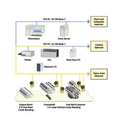
Two-dimensional-array scanners situated at various points in a manufacturing process feed real-time production data via Ethernet to plant and enterprise systems, allowing companies to track inventories, boost throughput and save money. Courtesy of Cognex Corp.
“It is a challenging machine vision application. You’ve got a lot of different part surfaces out there,” acknowledged Carl Gerst, manager of ID products marketing at Cognex Corp. in Natick, Mass. Nonetheless, he projected that the company would double its ID business this year as compared with last year.
Furthermore, ease of use is improving. Several years ago, Gerst recalled, his company would have to send an applications engineer to clients to set up the cameras, lighting and system for part mark identification. Thanks to advances in software and lighting, that’s no longer the case. In fact, setting up a 2-D system now is only as difficult as setting up a one-dimensional, or linear, bar-code scanner, he said.
On the technical side, Gerst said that a good rule of thumb is that a 2-D matrix of marks will take up about one-tenth the space of the stripes and spaces of the more familiar linear bar code. Suppliers expect the same reading accuracy rates — 6 σ, or an error rate <1/100 percent — for the 2-D array as those achieved by linear bar codes.
For its part, Cognex offers fixed-mount, 640 × 480- and 1024 × 768-pixel CCD cameras running its proprietary IDMax software to read the part marks. The company also offers handheld units that use CMOS sensors. The choice of sensors is based upon required read rates, sensitivity, power and cost.
As for why this application is so popular, Gerst noted that better tracking of inventory allowed an engine manufacturer to boost production more than 50 percent and to save millions of dollars a year. Along with continued demand from the defense and auto manufacturers, these benefits will continue to drive adoption and development of 2-D part mark identification.
Although many of the cameras used to identify parts are VGA resolution — 640 × 480 pixels — that may not be the case for very long. A desire for a larger field of view is driving the industry toward almost-2-megapixel cameras. Cognex, for example, plans to introduce cameras with 1024 × 768- or 1600 × 1200-pixel resolution.
CCD-based systems
Redlake MASD LLC of San Diego also is active in the multimegapixel-camera area. Although it is involved in the direct part mark identification market, it primarily concentrates on high-speed, high-resolution and multispectral cameras.

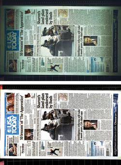
Redlake MASD’s imaging system corrects for various distortions — such as those caused by lenses and lighting (top) — that would otherwise impede machine vision. Flat-field correction (bottom) is achieved through a field-programmable gate array chip that doesn’t affect frame rates. Courtesy of Redlake MASD LLC.
Keith Russell, the company’s director of marketing, said that its products capture an image, which is then transferred to an external computer where image processing takes place. The size of the images — up to 11 megapixels, in some cases — is needed for such applications as flat panel display and semiconductor part inspection.
Redlake’s MegaPlus II products are all CCD-based systems. The company supplies cameras that correct for lens, lighting and other distortions that hamper machine vision and part inspection. This flat-field correction is done through a field-programmable gate array chip and doesn’t affect overall frame rates.
Most of its cameras contain a single sensor chip and capture color with a filter over each pixel. Typically, this is done using a Bayer pattern — an alternating grid of red, green and blue filters in which green accounts for 50 percent of the array. However, the company also offers cameras with three CCD chips. For those cameras, a prism and filters split incoming light into red, green and blue, or RGB, components. Each chip then captures a full-resolution image of one color. The complete color image is created by combining the output of all three chips.
Other software transforms the Bayer pattern into true RGB, but using a Bayer pattern reduces resolution by throwing away pixels. “The pixels are covered with red, blue and green filters. So you don’t get the sensor’s full resolution,” Russell said. “With a three-chip camera, our customers can take advantage of the sensor’s maximum resolution.”
He added that assembling a three-chip camera required care to achieve an optical alignment of sensor chips of less than a pixel. The cost of the three-chip devices is roughly triple that of a single-chip product; nonetheless, Russell asserted that there is a market for such products, and that the company plans to expand its three-chip product line.
Mapping the real world
Besides increasing resolution, machine vision vendors are striving to make their products more intelligent. Smart cameras from DVT Corp. of Duluth, Ga., for example, use multiple embedded processors. These devices handle such tasks as capturing and processing an image while communicating with the outside world. During operation, there is no need for an external host.

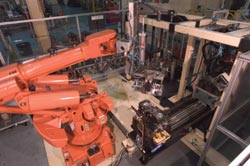
Equipping robots with integrated vision systems reduces the environmental-engineering requirements and increases work-space flexibility. The camera mounted on the vertical post to the right provides visual coordinates that are correlated with the robot’s internally programmed coordinates. Courtesy of DVT Corp.
That computational power can also be used to make robots and cameras cooperate. Typically, robots have limited senses and work in environments that have been carefully engineered. Equipping a robot with vision would increase work-space flexibility and pay other dividends.
“With vision, you can reduce the amount of environmental engineering you need because you identify the variation and correct for it. Plus, you can actually inspect your part at the same time,” said Rob Burridge, senior research and development engineer at DVT.
Even though this sounds simple, it can be complex. A robot manipulator, for example, usually has an internal coordinate system, so it knows where it is at any given time. A machine vision system, on the other hand, works with an image and uses that coordinate system. The difficulty lies in translating what the camera sees into the robot’s coordinate system. In the past, this had been a slow, error-prone, manual process that had to be repeated if the setup changed.

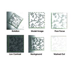
Scanners must be designed to overcome imaging problems resulting from degradation of the 2-D array or to such background issues as low contrast, incorrect orientation of scanner and matrix, or poor focus. Courtesy of Cognex Corp.
The company’s latest version of its Intellect software includes an innovation that Burridge developed to tackle this task. Although various methods can be used to mark samples, he said, the simplest is to use a 2-D array of dots, which provides a coordinate grid and a scale from which the software correlates the real world and what the camera sees. This reduces to a single click what had been up to a half-hour-long manual process of calibration between camera and robot.
Mapping innovation
Another result is nonpixel-based measurement. For example, a circle may look like a narrow ellipse because of the angle of the camera. Thanks to this mapping transformation, the software can recreate the circle’s original dimensions.
DVT is working with a number of robotics companies, including Kuka Robotics Corp. of Clinton Township, Mich., and Yamaha Robotics of Edgemont, Pa. DVT’s goal is to have a drop-down menu option that would allow users to match a camera to a robot during setup. Such a capability could be the start of new machine vision functionality.
Consequences, Intended and Not
The growing power and sophistication of machine vision tools is evident in a number of areas. One is the use of machine vision in endeavors too costly for general-purpose solutions. For example, Checker, by Cognex Corp. of Natick, Mass., is an all-in-one system that integrates lighting, lens and part detection into a single unit. The product runs at a high speed, accepting or rejecting as many as 3600 parts per minute.
According to Cognex product marketing manager John Keating, the product gives users a yes/no answer about parts moving past its sensors. “Checker is specifically designed to solve one problem: ‘presence’ or ‘absence,’” he explained.
Another expanding area is nontraditional machine vision tasks, such as deciphering handwriting. ActivOCR from MVTec Software GmbH of Munich, Germany, claims an out-of-the-box recognition rate of almost 99 percent — much higher than the 95 to 96 percent typical of other neural network classifiers.
Wolfgang Eckstein, MVTec’s managing director, said the philosophy behind such technologies is literally simple. “More and more users without a deep technical background want to use machine vision. This requires new approaches to ease the use of these systems.”
However, there are also some unintended consequences of these greater capabilities. David Wyatt, president of Midwest Integration of Mishawaka, Ind., noted that there is less need for system integrators precisely because of the power in machine vision products. That’s one reason why his company is a product distributor as well as a vision systems integrator.