
Laser Beam Diagnostics Is a Critical Step in University Research
Diagnostic cameras and specialized software can assess the quality and uniformity of a laser beam to ensure hot spots and other anomalies aren’t present.
DICK RIELEY, OPHIR
The scientific endeavors of our university systems are a vital part of the industrial R&D process that produces many of today’s leading-edge designs and manufacturing processes. Much of that development involves lasers of all sizes and types, from deep UV to terahertz, and power density requirements from a few µW/cm2 to several MW/cm2. The demand to accurately measure these concentrated light forms is endless and limitless. So it is up to the researcher to understand the value of particular lasers that will be considered, which wavelengths are best for the absorption of the material or gasses involved, how much power from the laser source is needed to perform the activity required, and the size, shape and uniformity of the laser beam itself.
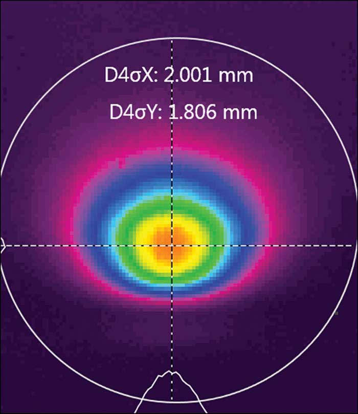
Figure 1. In some cases, a laser beam is not uniform and does not possess the correct ellipticity.
In a specialized process that requires a specific type of laser, the quality of the final output will largely be a result of the effect of the diameter of the laser beam and its power density. The uniformity and consistency of the delivered power across the beam must be done in such a way as to eliminate hot spots or other beam anomalies that produce undesired results.
In some cases, the laser beam is not uniform and does not possess the correct ellipticity. This could be due to poor setup by the laser manufacturer, alignment issues not properly addressed or damaged optics in the laser head.
It’s not uncommon to find a process that requires a circular beam, but the beam profile shows a flat side on the southern edge (Figure 1). Here, the beam is 0.2-mm greater in the X axis than in the Y axis; because of this difference, if the analysis of the process requires the movement of the beam in the X direction, the results will be dramatically different than when moved in the Y direction. Whether the process is ablation, cutting or welding, this effect will, for example, produce a weld that only meets specification when moving in the north or south direction. Any movement in another direction will produce a weld of a diameter smaller than specified.
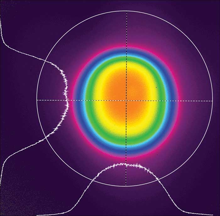
Figure 2. Here the beam is properly formed by the laser optics into a “top hat” pattern.
Surprisingly, this type of situation is not uncommon in the academic research community. Funding limitations are a big factor. Often, the majority of the funding for laser-based research focuses on the hardware: optical tables, optical equipment and lasers. Once all this is installed and operational, there is limited funding available for diagnostics to ensure the laser is performing up to specification. This would be akin to specifying and purchasing the perfect automobile, and then getting it delivered without a speedometer.
When proper diagnostic equipment is not available, the quality of the laser beam can only be determined by the end product or process. This can be a prohibitively expensive approach, depending on the materials involved.
Beam quality critical to ablation
In an ablating process, for instance, specialized material is removed in very precise amounts and in a uniform manner by the laser beam. If the beam is not properly formed by the laser optics into a “top hat” pattern (Figure 2), the resulting surface will be lined with minute ridges and valleys, a condition likely unacceptable to the research objective.
There is growing awareness of the methods required for testing and evaluating the laser beam quality, size, shape and uniformity. This includes the use of simple optical burn paper, where a sample shot of the laser is targeted onto black photographic paper and the burn pattern can, to some degree, indicate the size and shape of the laser beam (Figure 3).
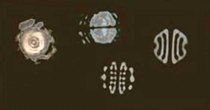
Figure 3. Optical burn paper uses burn patterns to indicate the size and shape of the laser beam.
The limitation to this technique is that, when involved with critical laser optics, the smoke from the very short burn process can settle ever so slightly onto the optical lens of the laser, potentially affecting the quality of the laser beam output. Smoke or other fumes around laser optics must be avoided.
Depending on the wavelength of the laser, another approach to understanding the essential elements of the beam is using a fluorescence plate. This is useful when working with UV wavelengths (<488 nm), as this allows the beam to be visibly imaged.
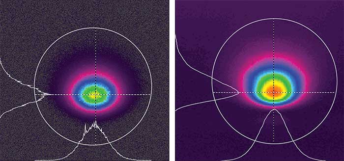
Figure 4. The use of a phosphorous-coated CCD array can produce an image of a very ragged beam profile (left). When using the high-resolution InGaAs array, the same image is displayed in a much truer form and shape (right).
This method presents problems if the researcher requires a true representation of the laser beam in this wavelength. For example, when imaging a 1550-nm beam onto a phosphorous-coated Si CCD array, there will be a very ragged beam profile. When imaging using the high-resolution InGaAs array, however, the same image is shown in a much truer form and shape (Figure 4).
In some applications, the size of the laser beam is too large for a typical beam profiling instrument or camera. The use of a diffusing glass plate is a reasonable approach along with a standard CCD beam profiling camera mounted with a reducing, focusing lens that converges the beam onto a clear profile for measurement of size, shape and uniformity. An example is profiling a white light that is approximately 100-mm in diameter, a size that no affordable beam profiler camera with a 7 × 5-mm array can handle (Figure 5).
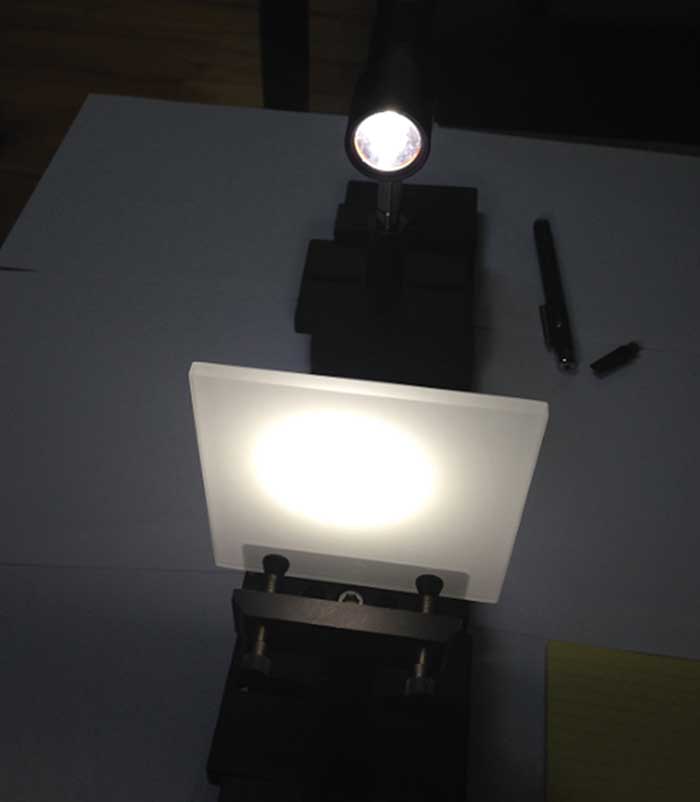
Figure 5. Profiling a white light that is approximately 100-mm in diameter.
Here, an LED lamp is used to project an image about 100-mm in diameter onto the diffusing glass plate. The beam profiling camera, with the focusing lens mounted, is positioned opposite the image plane (Figure 6).
Once aligned, the beam profile, which to the human eye is a consistent white light, displays the nonuniformity of the shape and its intensity (Figure 7).
Beam diagnostics for multiple lasers
In a typical research facility, multiple lasers are in use. That means multiple optical layouts are required, as well as a detailed understanding of the particular character of each laser and how it is used for each test arrangement.
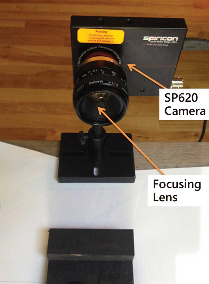
Figure 6. An LED lamp is used to project an image about 100-mm in diameter onto a diffusing glass plate.
Each laser requires testing and validating for each project, in order to ensure that the laser source is performing up to the manufacturer’s specification and the measurements of the resulting beam are up to expectations. It’s also important to establish a baseline of the laser’s performance for use against future measurements to determine if the laser has degraded or otherwise shifted in its performance.
This task puts a burden on the scientific lab to use commercially available tools in the most efficient manner, and yet allow for the funding of this equipment through the same program under which the laser sources were acquired. Unfortunately, when it becomes known that this type of laser performance information is needed, the laser systems are typically already in place, the scientific experiments are ready to be conducted, and any delays could be counterproductive to the guidelines of the grant. It is paramount to employ cost-effective, commercially available diagnostic equipment that is easy to use, quick to set up and provides the information needed for acceptance by the research staff as well as by the community reviewing the grant results.
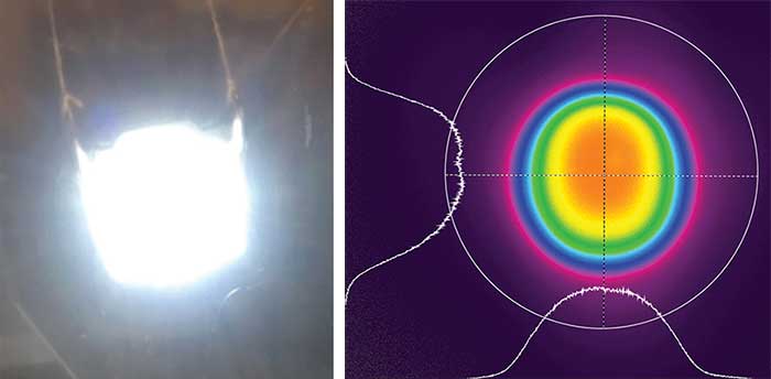
Figure 7. Once aligned, the beam profile, which to the human eye is a consistent white light (left), displays the nonuniformity of the shape and its intensity (right).
For example, a university was required to evaluate the effectiveness of ablating certain exotic coatings from a ceramic substrate and so had acquired three different lasers, all typically <5 mW. The challenge arose in that the wavelength of the laser sources spanned a large range. The first laser was a 700-nm source with about a 3-mm diameter beam. The second was a 1300-nm source with a beam diameter about 3-mm. The third laser was an 1800-nm source with a 0.88-mm beam diameter.
Upon initial investigation by the researcher, the university procured an expensive beam diagnostic system that yielded sufficient results, but at a price. Two beam profile cameras were selected: one for use on the 700-nm source, and a second for use on the 1300- and 1800-nm sources.
The budget was tight after procurement of the lasers, leaving little for beam diagnostic test equipment. ?The solution for this researcher was the use of an InGaAs Spiricon XC130 camera (30 × 30-µm pixels, 320 × 256 array that is 9.6 × 7.6-mm in size). This camera, with its wide dynamic range, could be used effectively for all three wavelength tests: 700, 1300 and 1800 nm. It produced accurate results and provided a common base of equipment for staff testing. This particular diagnostic camera was selected based on a physical laboratory test of all three sources with this camera.
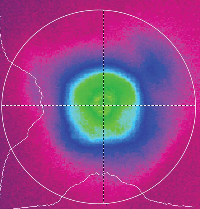
The sensitivity of the Spiricon XC130 InGaAs camera, using a feature of the software that allowed summing of 11 camera frames, provided sufficient imaging capability to view the beam and obtain accurate measurements.
Although the baseline specification for the camera reported the absorption sensitivity of the array from 900 to 1700 nm, previous testing showed that with sufficient power, the camera array could image below 900 nm, down to 700 nm, and upward to 1800 nm. The specification was firm, and the manufacturer did not offer any guarantees, so testing the applications was mandatory.
Test 1: The first test was conducted on the 700-nm source, with power measured at 281 µW of average power. The sensitivity of the camera, using a feature of the software that allowed summing of 11 camera frames, provided sufficient imaging capability to view the beam and obtain accurate measurements. Although the camera is not specified for the shorter 700 nm and 281 µW, it could be used for shorter wavelengths when used with the associated beam diagnostic software.
Test 2: It is possible to use a standard visible CCD profiling camera for an application at 1300 nm. However, due to the poor absorption of this wavelength by a silicon array, even with tens of milliwatts of power and a larger beam diameter, the resulting images do not possess the resolution necessary to be informative, and the beam measurements can be relative, at best. For these reasons, this source was also tested using the InGaAs camera and was easily imaged and profiled, as this wavelength is in the middle of the camera’s specified array absorption range.
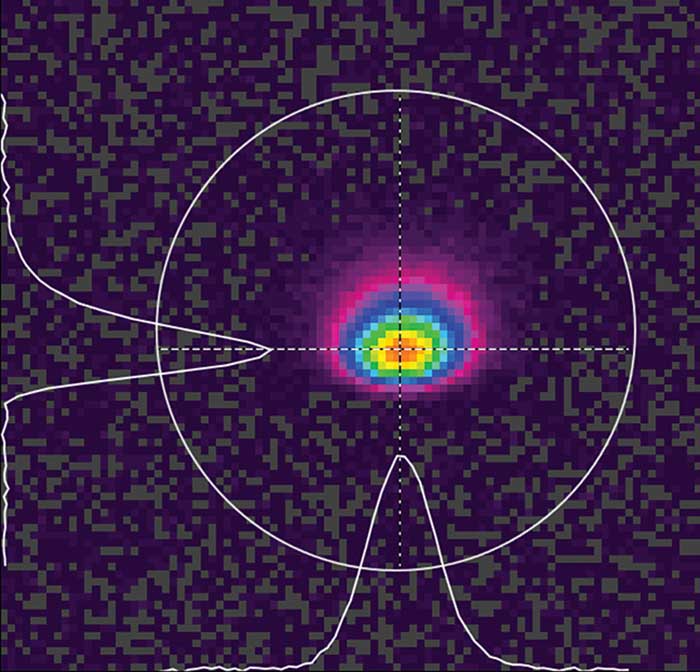
Here the wavelength was reported to be 687 µW of average power at 1800 nm, just beyond the specification of 1700 nm for the camera.
Test 3: The third laser source proved to be a challenge in that the wavelength was reported to be 687 µW of average power at 1800 nm, just beyond the specification of 1700 nm for the camera. The test proved inconclusive, at best. So the laser and camera were fixtured and then tested. The test proved that in this case, considering wavelength and power, a sufficient image and graphic measurement was possible.
Testing and validation of the lasers using a beam diagnostic camera and beam profiling software allowed the researcher to source one camera rather than two to cover these three setups. Testing the camera on each of the sources to prove it was possible to graphically image and measure each source was critical to the justification of the equipment. In this case, the researcher chose to push the limits of the equipment to determine if, in his applications, this solution made sense. In this case it did, but these results may not be typical. The researcher was able to prove that for this application one beam profiling camera, if pushed, can be used to solve an otherwise expensive problem.
Meet the author
Dick Rieley is a field sales engineer, mid-Atlantic region, for Ophir (U.S.). Previously, he served as sales manager for Vanzetti Systems and marketing manager for Belden Corporation. He holds a B.A. in Industrial Business Marketing from Miami University.
/Buyers_Guide/MKS_Ophir_Light_Measurement/c10765