According to ISO 11146, the M2 measurement of beam quality works as well for diode stacks as it does for well-collimated lasers.
Andreas Letsch and Dr. Adolf Giesen, Universität Stuttgart, Institut für Strahlwerkzeuge
The characterization of diode lasers becomes more and more important with the increasing number of industrial applications that depend on this type of laser. ISO 11146 provides the measurement procedures to characterize the propagation properties of laser beams. In this standard, the beam diameters are defined by the second-order moments of the power-density distribution, which can be measured with a CCD camera or other device. However, the measurement of the energy-density distribution of a diode laser is critical because of the high value of the beam propagation factor that results in a high divergence angle compared with a nearly diffraction limited beam.
About ISO 11146
Besides beam power and polarization, the transverse beam dimensions — defined by the second-order moments of the power-density distribution — and their change during propagation are the most important characteristics of laser beams. During the European Union’s two laser-beam and optics-characterization projects, CHOCLAB and CHOCLAB II (for “Characterization of Optical Components and LAser Beams”), ISO 11146 was established and evaluated for CW lasers in several experiments.
The measurements of power-density distributions and laser beam propagation parameters are covered by ISO 13694 and ISO 11146.1-3 These standards, the related theoretical and practical problems and especially the noise-induced errors in the determination of second-order moments have been extensively discussed at several conferences on laser beam characterization.4-8
Furthermore, some “round robin” experiments have been performed, where partners from various laboratories and industrial companies characterized the same laser beam source according to the proposed standards, with the goal to test and verify the applicability of the proposed standard measurement procedures to industrial laser systems.9-13 The characterization of highly divergent beams was studied in a round-robin test on a high-power fiber-coupled CW Nd:YAG laser and a high-power stacked array diode laser.13 This test indicated that the standard can be applied to such beams. So the proposed standards are well-validated for CW lasers in industrial applications.
Test procedures
The transverse beam dimensions are defined in ISO 11146 in terms of the centered second-order moments of the power-density distribution. These can be determined by:

where P denotes the total beam power, <x> and <y> the beam centroids, and E(x,y,z) the power-density distribution. The sum of the nonnegative integers m and n is 2, which means that there are three second-order moments, (x2 ), (y2 ) and (xy). These are related to the lateral extent of the power-density distribution of the beam in the measurement plane. Therefore, the beam widths of an elliptical beam in x- and y-direction are given by:

The determination of second-order moments is usually done experimentally by measuring the power-density distribution and a subsequent numerical evaluation. It is well-known that, because of the parabolic weighting (equation 1), this process is extremely sensitive to measurement errors. To achieve reasonable accuracies, ISO 11146 gives detailed provisions on this test procedure. The spatial resolution of the measurement device should be adapted to the spatial structure of the beam, the dynamic range should be chosen appropriately high, and the sensor should acquire more than 99 percent of the total beam power to avoid errors caused by clipping. The last requirement usually can be met if the detector size is at least twice the beam diameter. Furthermore, data preprocessing is necessary to correct for background signals and noise.
The free-space propagation law for the second-order-moment beam diameter reads:

At the waist (z = z0), the beam reaches its minimum diameter d0, and with increasing distance from the waist, it starts spreading with the divergence angle . The transverse propagation properties of any stigmatic beam are fully described by the beam waist d0, the distance from the waist z and the divergence angle θ.
The product of divergence angle θ0,0 and the beam waist width d0,0 of a fundamental laser beam (TEM00) is constant and depends only on the wavelength l:

The phenomenon of optical diffraction dictates that this constant is the smallest product of divergence and beam waist. Therefore, such a fundamental laser beam also is called diffraction-limited. The laser beam propagation factor M2 is defined as the ratio of the products of divergence angle and beam waist of the measured beam to the product of the fundamental beam:

The beam propagation factor of the fundamental mode is 1, and for any real beam, ≥1. So the M2 value relates the focusability of the beam under test, compared with a Gaussian beam of the same wavelength.
The propagation of a simple astigmatic beam can be expressed by two analogous expressions to equation 4, which describe the propagation along the two principal axes of the beam. Therefore, seven parameters are needed to characterize a simple astigmatic beam; one describes the orientation φ of the principal axes with respect to the laboratory coordinate system and six beam parameters (d0,x, d0,y, θx, θy, z0,x, z0,y ).
The combined determination of all beam propagation parameters according to ISO 11146 has to be performed by recording the free-space propagation of the beam widths. The beam parameters are then obtained from a hyperbolic fit to the measured data. Because the achievable accuracy of the beam parameters strongly depends on the number and positions of the measurement planes with respect to the beam waist, ISO 11146 gives detailed provisions.

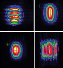
Figure 1. To show the power-density distributions of the diode stack, these beam profiles were captured (from upper left to lower right) within one Rayleigh length of the beam waist, at two positions near the beam waist and at one Rayleigh length after the waist.
At least five measurement planes should be near the beam waist (within one Rayleigh range) for accurately determining the waist diameter. At least five additional measurement planes in a distance more than two Rayleigh lengths away from the beam waist are necessary for accurate determination of divergence angle and waist position. If the measurement planes are arranged nearly symmetrically around the beam waist, the accuracies can be further increased.
Diode stacked array measurement
The Jenoptik 230-W diode stacked array consisted of six bars, each 10 mm wide, with fast- and slow-axis collimation and redirectors to reduce the M2 value of the slow axis, which simultaneously increases the M2 value of the fast axis. The diode wavelengths were about 940 nm. The collimated laser beam was attenuated by reflection from the front plane of two uncoated fused-silica wedges at small angles. This attenuated beam was focused with a 310-mm lens and an 88-mm lens to the measurement planes.

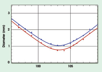
Figure 2. In this illustration of the measured beam diameters of the diode stack, the blue curve shows the slow axis of the beam and the red curve, the fast axis.
A 12-bit CCD camera was used to capture the power-density distributions of a simple astigmatic beam (Figure 1). An almost circular and smooth power-density distribution was measured at the beam waist. At distances of about one Rayleigh length away from the waist, the beam profile is almost rectangular and strongly modulated. The relative deviation of the measured beam diameters to the fitted parabola is less than 5 percent (Figure 2). The M2 beam-propagation factors of the two principal axes, calculated directly from these data, are 210 and 310.
It has been clearly demonstrated that ISO 11146 can be applied not only to “simple” laser beams, but also to laser beams with multiple sources and strongly modulated power-density distributions. Using this characterization technique, it is therefore possible to describe the complete beam propagation behavior and the focusability of such beams in an elegant and nonambiguous way. This has been demonstrated in many experiments, and this laser diode stacked array is a good example of the standard’s application.
References
1. ISO 11145 — Vocabulary and symbols.
2. ISO 11146 — Test methods for laser beam parameters: Beam widths, divergence angle and beam propagation factor.
3. ISO 13694 — Test methods for laser beam parameters: Power (energy) density distribution.
4. (1993). Proceedings of the First Workshop on Laser Beam Characterization. P.M. Mejìas, ed. SEDO, Madrid, Spain.
5. (1994). Proceedings of the Second Workshop on Laser Beam Characterization. H. Weber, ed. Festkörper-Laser-Institut, Berlin.
6. (1995). Beam control, diagnostics, standards and propagation. W.A. Austin, ed. Proc. SPIE, Vol. 2375.
7. (1996). Proc. SPIE Third International Workshop on Laser Beam and Optics Characterization. M. Morin and A. Giesen, eds. Vol. 2870.
8. (1997). Proceedings of the Fourth International Workshop on Laser Beam and Optics Characterization. A. Giesen and M. Morin, eds. Munich. VDI-TZ.
9. B.A. Ward, S. Assa, B.W. Davis, C.B. Edwards and P. Muys, (1995). Investigation of the M2 measurement of CO2 laser beams. Proc. SPIE Beam Control, Diagnostics, Standards and Propagation, Vol. 2375.
10. H. Bartels, P. Börger, F. Dorsch et al (1996). Characterization of an industrial CO2 laser: Results of a workshop within the EUREKA project EU-1269 “CHOCLAB.” Proc. SPIE Third International Workshop on Laser Beam and Optics Characterization. M. Morin, and A. Giesen, eds. Vol. 2870.
11. U. Habich, M. Scholl, H. Müntz et al (1997). Evaluation of camera data: Results of a round robin test. Proceedings of the Fourth International Workshop on Laser Beam and Optics Characterization. A. Giesen and M. Morin, eds. Munich.
12. R. Mästle, B. Eppich, U. Habich et al (1997). Results of two round-robin-experiments on laser beam characterization within the EUREKA project EU-1269 “CHOCLAB. ”Proceedings of the Fourth International Workshop on Laser Beam and Optics Characterization. A. Giesen and M. Morin, eds. Munich.
13. R. Mästle, A. Letsch, M. Brandner, B. Eppich, W.-D. Scharfe, H. Schwede and K. Spennemann (2001). Results of a round-robin experiment on the characterization of highly divergent beams. Proceedings of the Sixth International Workshop on Laser Beam and Optics Characterization. Edited by Wissenschaftliche Gesellschaft Lasertechnik eV.
Meet the authors
Andreas Letsch works on laser beam characterization at the Institut für Strahlwerkzeuge at Universität Stuttgart in Germany; e-mail: [email protected].
Adolf Giesen is head of the laser development department at the institute; e-mail: [email protected].